78
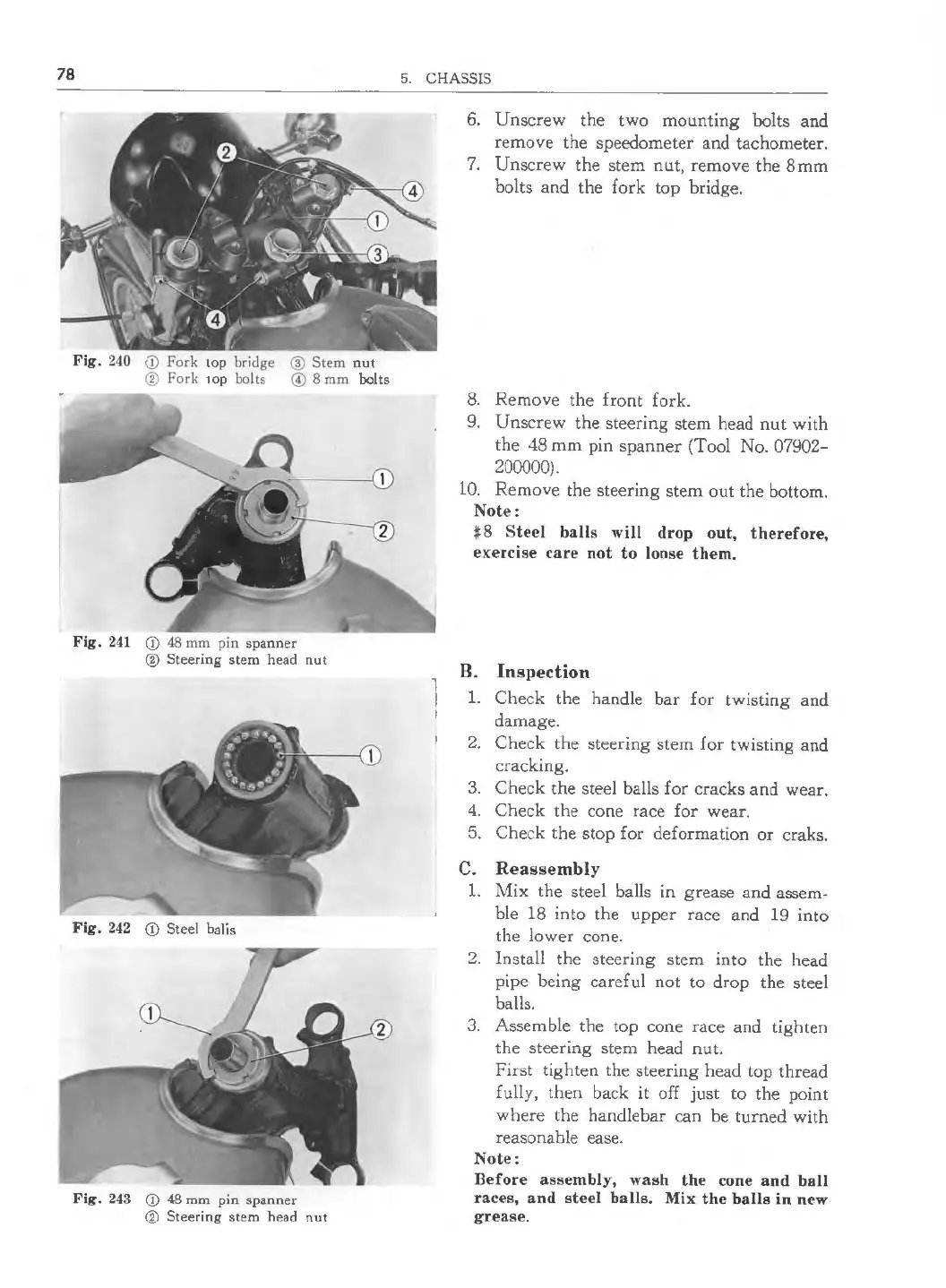
Fig. 240 <1) Fork top bridge @ Stem nut
@ Fork 1op bolts © 8 mm bolts
Fig. 241 CD 48 mm pin spanner
@ Steering stem head nut
Fig. 242 CD Steel balis
Fig. 243 CD 48 mm pin spanner
@ Steering stem head nu t
5. CHASSIS
6. Unscrew the two mounting bolts and
remove the speedometer and tachometer.
7. Unscrew the stem nut, remove the 8mm
bolts and the fork top bridge.
8. Remove the front fork.
9. Unscrew the steering stem head nut with
the 48 mm pin spanner (Tool No. 07902-
200000).
10. Remove the steering stem out the bottom.
Note :
#8 Steel balls will drop out, therefore ,
exe rcise care not to loose them.
B. Inspection
1. Check the handle bar for twist ing and
damage.
2. Check the steering stem for twisting and
cracking.
3. Check the steel balls for cracks and wear.
4. Check the cone race for wear.
5. Check the stop for deformation or craks.
C. Reassembly
1. Mix the steel balls in grease and assem-
ble 18 into the upper race and 19 into
the lower cone.
2. Install the steering stem into the head
pipe being careful not to drop the steel
balls.
3. Assemb le the top cone race and tighten
the steering stem head nut .
First tighten the steering head top thread
fully, then back it off just to the point
where the handleba r can be turned with
reasonable ease.
Note :
Before assembly, wash the cone and ball
races, and steel balls . Mix the balls in new
grea se.
 Loading...