:,•,,n , .. 1,.,1o,,1,,11,,l,,, 11,,11,,1lu1lo11h,11o,11u1,.,11,,11,,1 1.,,1,,11,,1 .. ,h~
j 6. ELECTRICAL t
{, •• , .......... . ,, .. 11••,, .. , ... , •.••••• , ••• , ••••••• , ••• , •. 11,,,,, •• , ... , ...... ,, .. 11,~
1. GENERAL DESCRIPTION
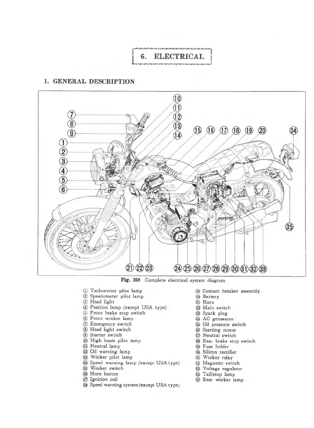
Fig. 269 Complete electrical system diagram
<D Tachometer pilot lamp
® Speedometer pilot lamp
@ Headlight
© Position lamp (except USA type)
® Front brake stop switch
® Front winker lamp
(f) Emergency switch
® Head light switch
® Starter switch
@) High beam pilot lamp
@ Neutral lamp
@ Oil warning lamp
@ Winker pilot lamp
@ Speed warning lamp (except USA type)
@ Winker switch
@ Horn button
@ Ignition coil
@ Speed warning system (excep t USA type)
@ Contact breaker assembly
® Battery
@Horn
@ Main switch
@ Spark plug
@ AC generator ·
@ Oil pressure switch
@ Starting motor
@ Neutra l switch
@ Rear brake stop switch
@ Fuse holder
@) Silicon rectifier
® Winker relay
@ Magnetic switch
@ Voltage regulator
® Tail/stop lamp
@ Rear winker lamp
 Loading...