I
Lubrication Svstem
I
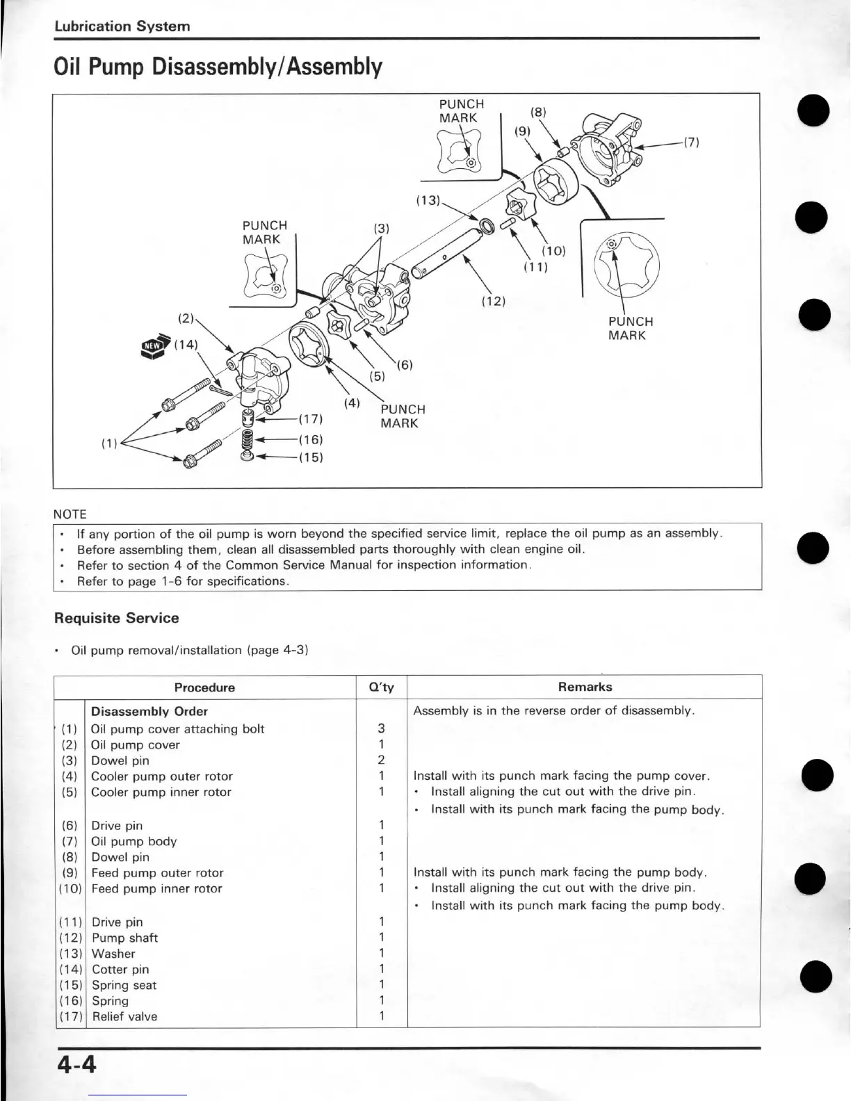
Oil Pump Disassembly/Assembly
PUNCH
PUNCH
MARK
NOTE
.
If any portion of the oil pump is worn beyond the specified service limit, replace the oil pump as an assembly.
-
Before assembling them, clean all disassembled parts thoroughly with clean engine oil.
Refer to section
4
of the Common Service Manual for inspection information.
-
Refer to oaoe
1-6
for soecifications.
Requisite Service
Oil pump removal/installation (page
4-3)
Procedure
(3)
(4)
(5)
(1
1
)
Drive pin
11
2)
PU~D shaft
1
i
Q'W
3
1
(1)
(2)
Dowel pin
Cooler pump outer rotor
Cooler pump inner rotor
(6)
(7)
(8)
(9)
(10)
Remarks
Assembly is in the reverse order of disassembly.
Disassembly Order
Oil pump cover attaching bolt
Oil pump cover
Drive pin
Oil pump body
Dowel pin
Feed pump outer rotor
Feed pump inner rotor
2
1
1
1
1
1
1
1
1
lnstall with its punch mark facing the pump cover.
.
lnstall aligning the cut out with the drive pin.
.
lnstall with its punch mark facing the pump body.
Install with its punch mark facing the pump body.
-
lnstall aligning the cut out with the drive pin.
lnstall with its punch mark facing the pump body.
(13)
(1
4)
(1 5)
(16)
(1
7)
washer
Cotter pin
Spring seat
Spring
Relief valve
1
1
1
1
1
 Loading...