Do you have a question about the Honda NSS250S and is the answer not in the manual?
General information regarding service and repair procedures.
Importance of proper service for customer safety and vehicle reliability.
Guidance for users on shop safety practices and self-assessment.
Key safety practices to follow when performing service tasks.
Guidelines for using parts, tools, and following procedures for safe service.
Information on how to identify the scooter's model using serial numbers.
Detailed technical specifications of the scooter's components and systems.
Specifications for the engine's lubrication system.
List of standard torque values for various fasteners and components.
Illustrations and instructions for proper routing of cables and harnesses.
Explanation of the scooter's lubrication system and its components.
Overview and operation of the smart card key system.
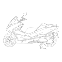
Illustration showing the location of various body panels on the scooter.
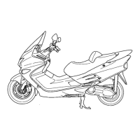
Step-by-step guide showing the order of body panel removal.
General information and precautions for servicing the frame, body, and exhaust system.
General safety precautions and notices for performing maintenance.
Recommended maintenance intervals based on time and odometer readings.
Instructions for checking and adjusting throttle grip freeplay.
Diagram illustrating the flow of lubricating oil through the engine system.
General information and precautions for servicing the lubrication system.
Common problems and their probable causes related to the lubrication system.
Illustration showing the location of PGM-FI system components.
General information and precautions for servicing the fuel system.
Guide to diagnosing and resolving common PGM-FI system symptoms.
Diagram showing the coolant flow path within the cooling system.
General information and precautions for servicing the cooling system.
Common cooling system problems and their causes.
Illustration showing the location of engine mounting components.
General information and precautions for engine removal and installation.
Step-by-step instructions for removing the engine from the frame.
Illustration showing the location of cylinder head and valve components.
General information and precautions for servicing the cylinder head and valves.
Common cylinder head and valve problems and their causes.
Illustration showing the location of cylinder and piston components.
General information and precautions for servicing the cylinder and piston.
Common cylinder and piston problems and their causes.
Illustration showing the location of drive pulley, driven pulley, and clutch components.
General information and precautions for servicing the drive pulley, driven pulley, and clutch.
Common problems related to the drive pulley, driven pulley, and clutch.
Illustration showing the location of final reduction components.
General information and precautions for servicing the final reduction system.
Common problems related to the final reduction system.
Illustration showing the location of alternator, starter clutch, and crankshaft position sensor.
General information and precautions for servicing the flywheel, alternator, starter clutch, and sensors.
Common problems related to the starter motor and engine not turning.
Illustration showing the location of crankcase, crankshaft, and balancer components.
General information and precautions for separating and assembling crankcase halves.
Common abnormal noises related to the crankcase, crankshaft, and balancer.
Illustration showing the location of front wheel, fork, handlebar, and steering stem components.
General information and precautions for servicing the front wheel, fork, and steering stem.
Common problems related to hard steering, wheel wobble, and suspension noise.
Illustration showing the location of rear wheel, parking brake, and suspension components.
General information and precautions for servicing the rear wheel, parking brake, and suspension.
Common problems related to rear wheel wobble, soft/stiff suspension, and brake noise.
Illustration showing the location of front and rear hydraulic brake components.
General information and precautions for servicing the hydraulic brake system.
Common problems related to brake lever feel, brake drag, and brake squeaks.
Illustration showing the location of ABS system components.
Diagram illustrating the ABS system's electrical connections and components.
General information and precautions for servicing the ABS system.
Illustration showing the location of the battery and charging system components.
Diagram illustrating the battery and charging system's electrical connections.
General information and precautions for battery and charging system service.
Illustration showing the location of ignition system components.
Diagram illustrating the ignition system's electrical connections.
General information and precautions for servicing the ignition system.
Illustration showing the location of lights, meters, and switches.
General information and precautions for servicing lights, meters, and switches.
Common problems related to the VS sensor and combination meter.
Illustration showing the location of Honda Smart Card Key System components.
General information and precautions for checking the Honda Smart Card Key System.
Diagram illustrating the Honda Smart Card Key System's electrical connections.
Illustration showing the location of Honda S Matic System components.
General information and precautions for servicing the Honda S Matic System.
Common problems related to the Honda S Matic System, such as engine starting issues or poor acceleration.
Steps for diagnosing and resolving issues with engine starting.
Troubleshooting steps for diagnosing and resolving engine power loss.
Steps for diagnosing and resolving poor engine performance at low speeds.
| Displacement | 249 cc |
|---|---|
| Compression Ratio | 10.5:1 |
| Fuel System | PGM-FI electronic fuel injection |
| Starter | Electric |
| Transmission | V-Matic |
| Front Suspension | Telescopic fork |
| Front Tire | 110/90-13 |
| Rear Tire | 130/70-12 |
| Engine Type | Liquid-cooled, four-stroke, single-cylinder |
| Rear Suspension | Dual shocks |
| Front Brake | Disc |
| Rear Brake | Disc |
| Bore x Stroke | 72.7 mm x 60.0 mm |