MAINTENANCE
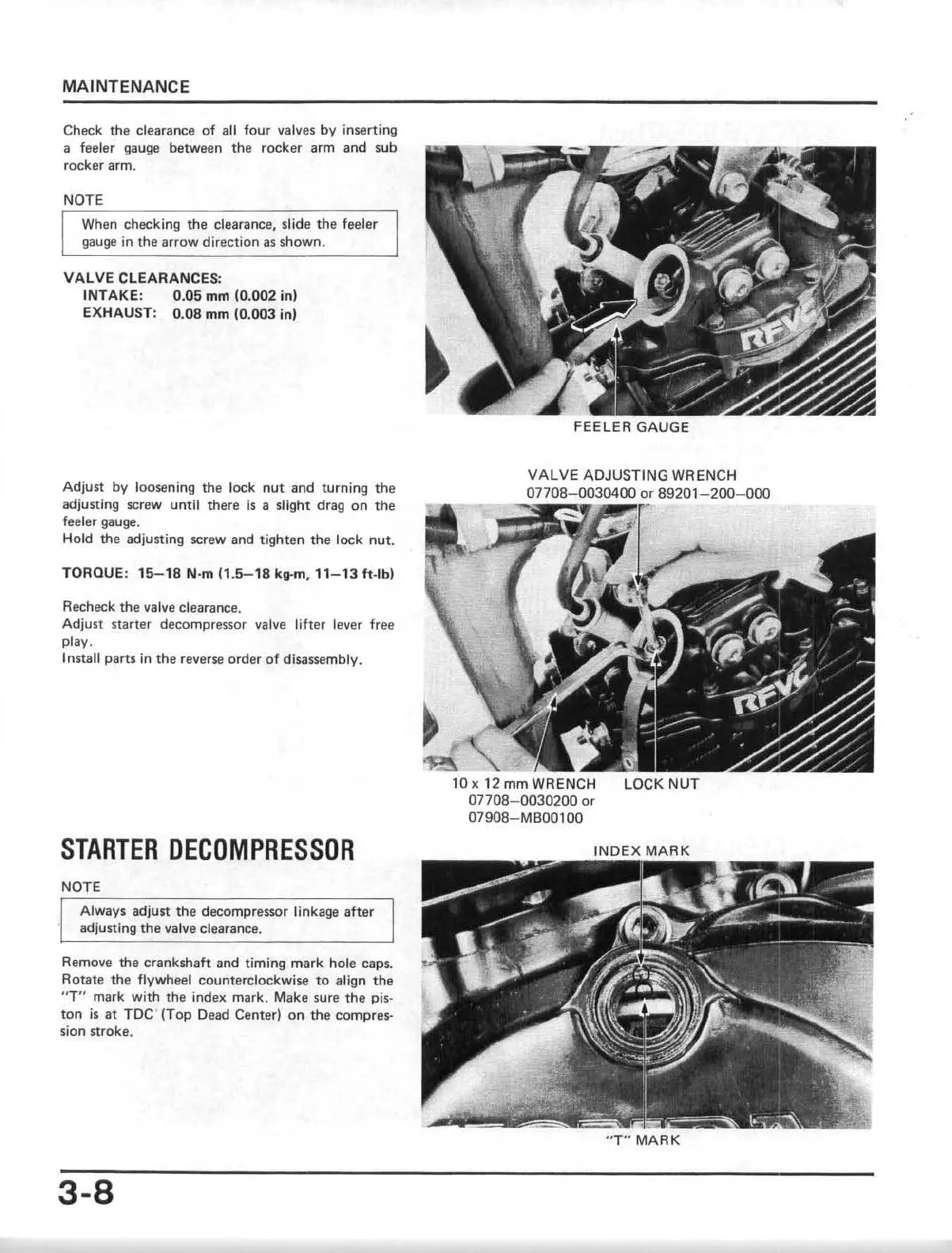
Check the clearance
of
all four valves by inserting
a feeler gauge between the rocker arm and sub
rocker arm.
NOTE
When checking
the
clearance, s
li
de the feeler
gauge
in
the arrow direction
as
shown.
VALVE CLEARANCES:
INTAKE
: 0.05 mm (0.002 in)
EXHAUST: 0.08 mm (0.003
inl
Adjust by loosening
th
e lock
nut
and turning the
adjusting screw until there
is
a slight drag
on
th
e
feeler gauge.
Hold the adjusting screw and tighten the lock nut.
TOROUE:
15-18
N'm
(1.5-18
kg.m,
1'-13
ft
-
Ibl
Recheck
the
valve clearance.
Adjust starter decompressor valve lifter lever free
play.
Install parts
in
the
reverse
or
der
of
di~ssembly.
STARTER
DECDMPRESSOR
NOTE
Always adjust the decompressor linkage after
adjusting
the
va
lve
clearance.
Remove
the crankshaft and timing mark hole caps.
Rotate the
flywheel counterclockwise to align
the
"T" mark with the index mark. Make sure
the
pis-
ton
is
at
TDC (Top Dead Center)
on
the compres-
sion stroke.
3-8
FEELER GAUGE
VALVE ADJUSTI
NG
WRENCH
0
7708-0030400
or
89201-200
- 000
10
x 12 mm WRENCH
07708- 0030200
or
07908-MB001oo
LOCK
NUT
"T"
MARK
 Loading...