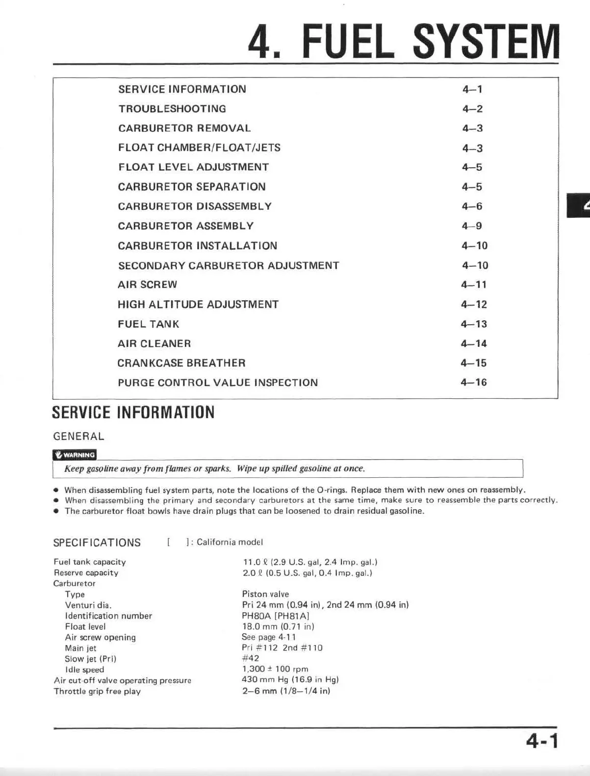
4.
FUEL
SYSTEM
SERVICE
INFORMATION
4-1
TROUBLESHOOTING
4-2
CARBURETOR
REMOVAL
4- 3
FLOAT
CHAMBER/
FLOAT
/J
ETS
4- 3
FLOAT
LEVEL
ADJUSTMENT
4-5
CARBURETOR SEPARATION
4-5
CARBURETOR DISASSEMBLY
4-6
CARBURETOR ASSEMBLY
4-9
CARBURETOR
INSTALLATION
4-10
SECONDARY CARBURETOR ADJUSTMENT 4- 10
AIR
SCREW
4-11
HIGH
ALTITUDE
ADJUSTMENT
4-12
FUEL
TANK
4-13
AIR
CLEANER
4-14
CRANKCASE BREATHER
4-15
PURGE CONTROL
VALUE
INSPECTION
4-16
SERVICE
INFORMATION
GENERAL
Keep gowline away from flames or sparks.
Wip
e up spilfell gasoline
or
once.
• When disassembling fuel system parts, n
ote
the
locations of the O-rings. Replace them
with
new
on
es
on
reassembly.
• When disassembling
the
primary
and
secondary
carburetors
at
th
e same time, make
sure
to
reassemble the
parts
correctly
,
• The carburet
or
fl
oat
bowls have
drain
plugs that can
be
loosened
to
drain
residual
gaso
l ine.
SPEC
IFICATIONS
I : California model
Fuel t
ank
capacity
Reserve capacity
Carburet
or
Type
Venturi dia.
Identification
nu
mber
Float
level
Air
screw opening
Main
jet
Sl
ow
jet
(Prj)
Idle speed
Air
cut-off
valve operating pressure
Throttle
grip free
play
11.0.Q
12.9 U.S. gal, 2.4 Imp, gaLl
2.0
~
(0.5 U.S. gal,
0.4
Imp
, gaL)
Piston
valve
Pr
j
24
mm
(0.9
4
in).
2nd
24
mm
(0.94 in)
PH
BOA
[P
HS1
A]
18.0
mm
(D.7l
in)
See
page 4-
11
Pri#1122nd#110
#42
1,300
± 1
00
rpm
430
mm
Hg
(16.9
in H
g)
2-6
mm
(1
/
8-1/
4 in)
4-1
•

 Loading...