LTEM-P Installation and Setup Guide
8
Mounting the Communicator
There are two mounting options:
• Mount the Communicator directly to a wall, secured with six screws and a wall tamper screw
• Mount the Communicator to a VISTA control panel cabinet, secured to the cabinet via a threaded
bushing and locking nut.
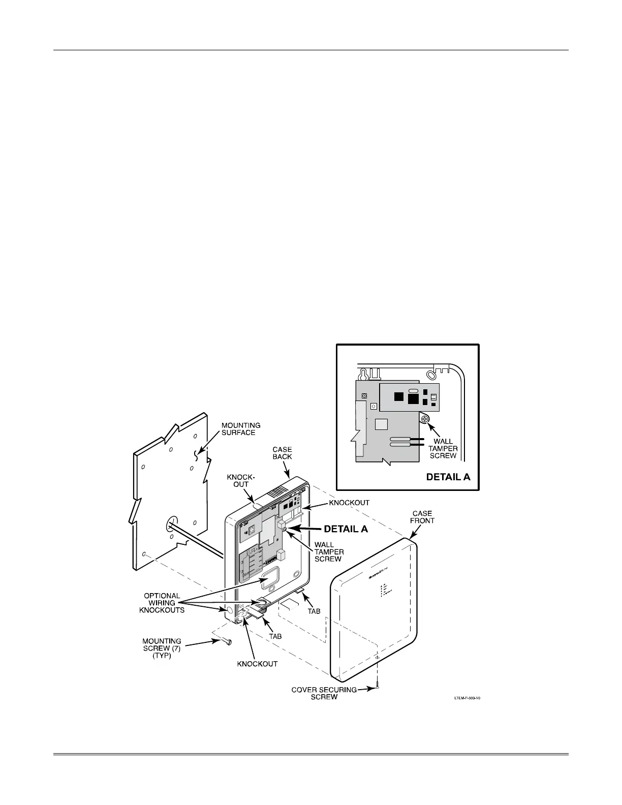
Mounting the Communicator on a Wall
1. Locate the case back over selected mounting position such that the opening in the case back is
aligned with the wire/cable opening on the mounting surface.
Pass the wires/cable through the opening in the case back, or route through the removable
knockouts located on the back cover.
NOTE: Cable tie anchor points are located on the case back around the large center knockout
(below the terminal block) for securing the wiring and providing strain relief.
2. Secure the case back to the mounting surface using six screws (3 along the top, 3 along the
bottom). After mounting, install the Wall Tamper screw. (Seven screws are provided.)
3. After all wiring is complete and the unit is powered up and the battery is connected, attach the
case front. Position the top first, then press the bottom section until it snaps in place. Secure
bottom using the supplied cover screw. (This is required for UL installations.)
Standard Mounting
 Loading...