Section 2: Mounting and Wiring
11
ECP & BUS Connection Maximum Wire Lengths
Minimum
Wire Gauge
Distance from
Control Panel
#22 75 ft (23m)
#20 120 ft (37m)
#18 170 ft (52m)
#16 270 ft (82m)
Wiring for Bus Connection Control Panels
For control panels that do not support ECP data communication, use the communicator's bus
terminals to connect the communicator to the control panel' data terminals. Check the control panel's
instructions for wire length/gauge limitations and refer to the ECP & BUS Connection Maximum Wire
Lengths table.
The following steps show typical connections. However, if using compatible DSC or Interlogix control
panels, refer to their respective sections below
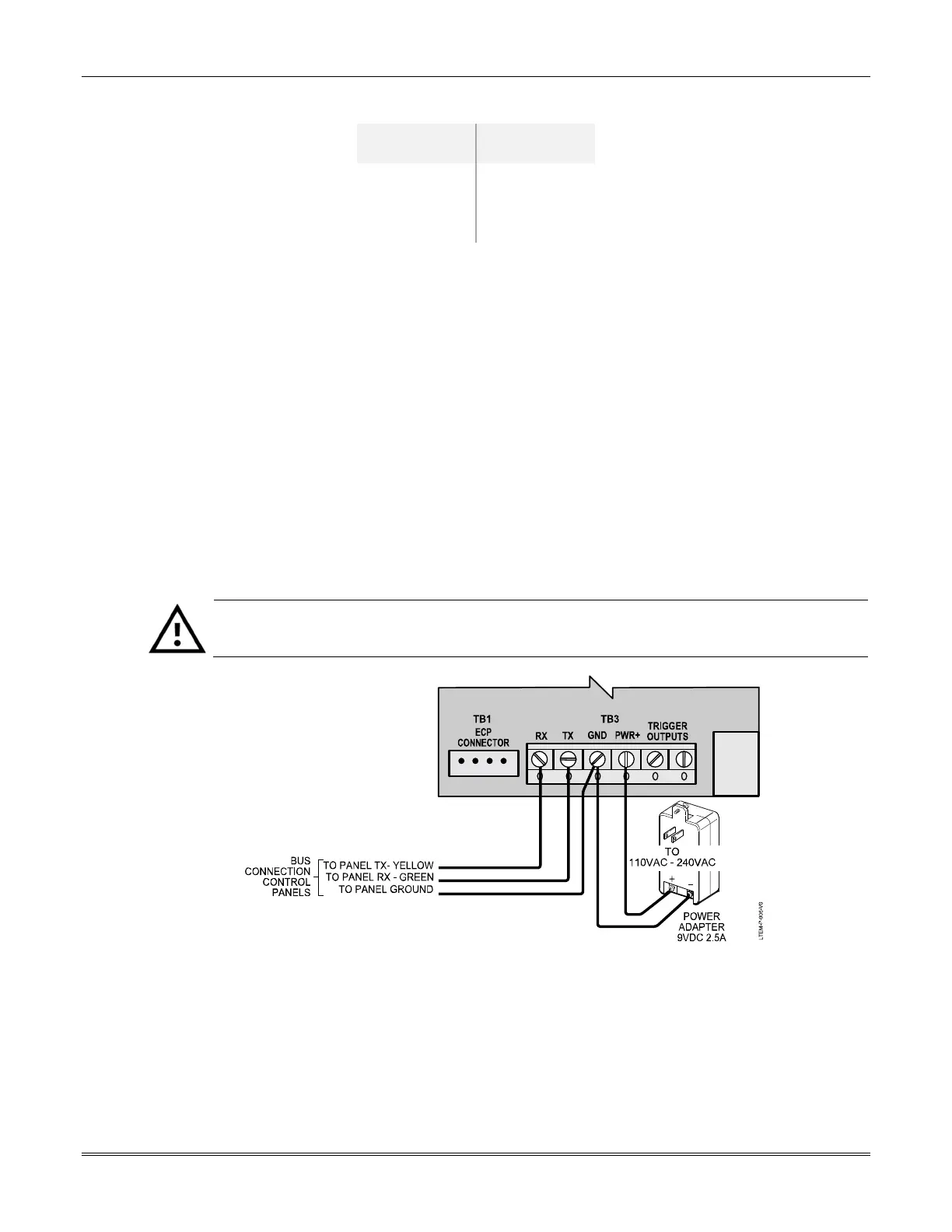
Typical Control Panel Bus Connections
1. Connect the communicator's RX, TX, and GND terminals to the appropriate terminals at the
control panel. See diagram below.
2. Connect the power adapter wires to the communicator's PWR
+
and GND terminals as shown.
Observe polarity.
3. Secure the wiring with cable ties as necessary. Cable tie anchor points are provided on the case
back below the terminal block.
The communicator is powered by the provided 9VDC Power Adapter only. Do not
connect power from the control panel to the communicator.
Wiring a Control Panel via Bus Connection Terminals
 Loading...