LTEM-P Installation and Setup Guide
14
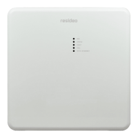
Power Connections
Connecting the Power Adapter
The communicator is powered from the supplied plug-in Power Adapter.
1. Connect the Power Adapter to the communicator's PWR
+
and GND terminals as shown below.
Observe polarity.
2. Power Up: After all wiring connections have been made and all optional plug-in modules have
been installed, plug the Power Adapter into a 24-hour, non-switched 110 - 240VAC outlet.
The communicator is powered by its 9VDC Power Adapter only. Do not connect power
from the control panel to the communicator.
Power Adapter Installation
Backup Battery
The included battery is used for backup in the event of power loss to the communicator. It does not
provide power to the control panel. The unit must be powered up before connecting the battery.
Battery Notes
• The battery can provide over 24 hours of
system life in the event of a power failure.
• A programmable power loss message can
alert the AlarmNet Control Center when
system power is lost (power loss messages are
reported within 1-3 hours of actual loss).
• The communicator transmits a low-battery
message (programmable) when the battery
reaches 3.8V ±5%, indicating subsequent
messages may not be transmitted.
• The system shuts down when the battery falls
below 3.3V, and radio transmissions are no
longer possible.
•
If system power is restored before the
communicator shuts down, a power restore
message is sent within 1-3 hours after power
is restored, and the battery is recharged using
the communicator’s built-in battery charger.
If system power is restored after the
communicator has shut down, a power-on
reset condition exists, the communicator
initializes itself and the battery will recharge.
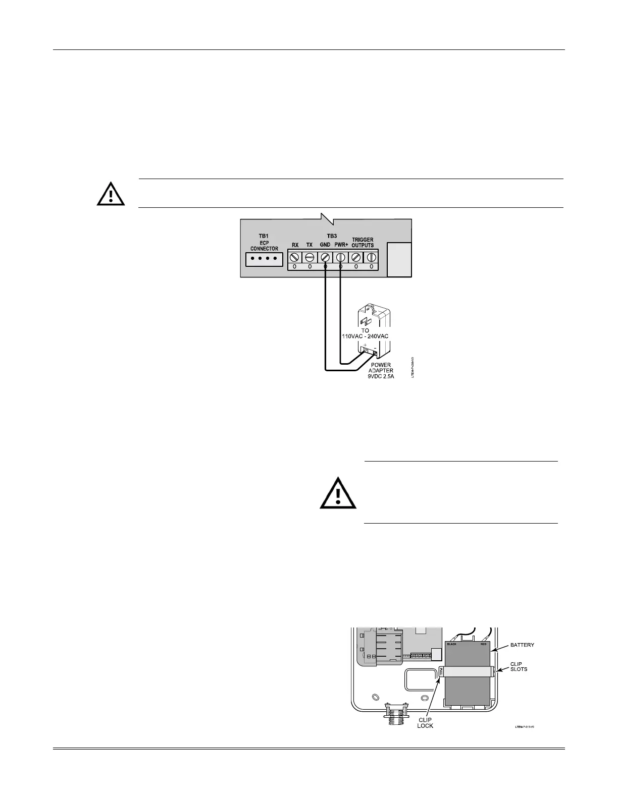
Install the battery as follows:
Do not plug the battery in until after the
communicator has been powered-up.
• Do not bend up the battery tabs.
• Battery replacement by professional
installer only.
1. Place the battery inside the case.
2. Hook the right side of the battery clip onto the
battery clip slots located on the case back,
then snap the left side of the clip onto the
battery clip lock.
3. Connect the battery to the communicator's
battery terminals. Observe polarity.
 Loading...