LTEM-P Installation and Setup Guide
12
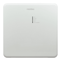
DSC Control Panel Connections
This section applies to the following DSC PowerSeries (PC) control panels:
• PC1616
• PC1832
• PC1864
1. Connect the control panel terminals labeled Black (BLK), Yellow (YEL), and Green (GRN) to the
communicator's GND, TX, and RX terminals respectively. See diagram below.
2. Connect the power adapter wires to the communicator's PWR
+
and GND terminals as shown.
Observe polarity.
3. Refer to the control panel's installation manual for details on programming the control panel.
After reboot/power up, the communicator takes about 5-7 minutes to complete the scan
of the panel's partitions and zones. The control panel must be in the "Ready" state (no
alarms or faults) in order to perform the scan.
The communicator is powered
by the provided 9VDC Power
Adapter only. Do not connect
power from the control panel
to the communicator.
Connections for DSC PowerSeries Control Panels
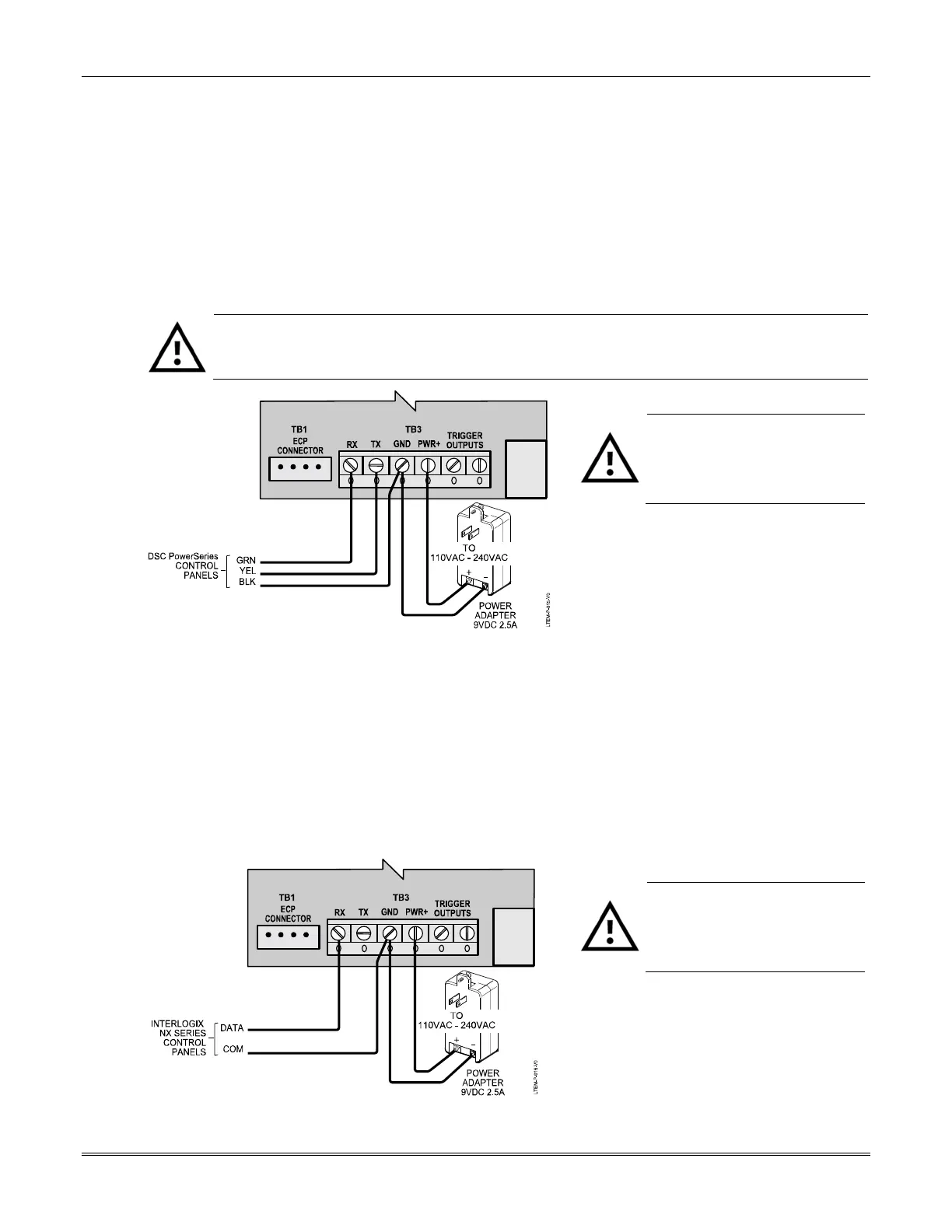
Interlogix Control Panel Connections
This section applies to the following Interlogix NetworX (NX) Series control panels:
• NX-8E • NX-4V2
• NX-6V2 • NX-8V2
1. Connect the control panel's DATA and COM terminals to the communicator's RX and GND
terminals respectively. See diagram below.
2. Connect the power adapter wires to the communicator's PWR
+
and GND terminals as shown.
Observe polarity.
3. Refer to the control panel's installation manual for details on programming the control panel.
The communicator is powered
by the provided 9VDC Power
Adapter only. Do not connect
power from the control panel
to the communicator.
Connections for Interlogix NX Series Control Panels
 Loading...