3
Power options
UWP Wiring terminal designations
S
Not used for T4
thermostat.
L/A
- A
Not used for T4 thermostat.
S
O/B Changeover valve
Y
Compressor contactor
(stage 1)
AUX -
W2
Auxiliary heat (TH4210U
only)
Y2
Not used for T4
thermostat.
E
Emergency heat (TH4210U
only)
G
Fan W Heat (stage 1)
C
24VAC common. For 2
transformer systems,
use common wire from
cooling transformer.
K
Connect to K on C-wire
adaptor**
U
Not used for T4
thermostat.
R
24VAC power from heating
transformer*
U
Rc
24VAC power from cooling
transformer*
Note: Not all
terminals may be
used, depending
on the system
type that is being
wired. The most
commonly used
terminals are
shaded.
* Terminal can be jumped using Slider Tab. See “Setting Slider Tabs” above.
** The THP9045A C-wire adaptor is used on heat/cool systems when you only have four wires at the thermostat,
and you need a fifth wire for a common wire. Use the K terminal in place of the Y and G terminals on
conventional or heat pump systems to provide control of the fan and the compressor through a single wire—the
unused wire then becomes your common wire. See THP9045 instructions for more information.
S
S
Y
2
U
U
G
C
Y
A
Rc
W
K
W2
R
L/A
O/B
AUX
E
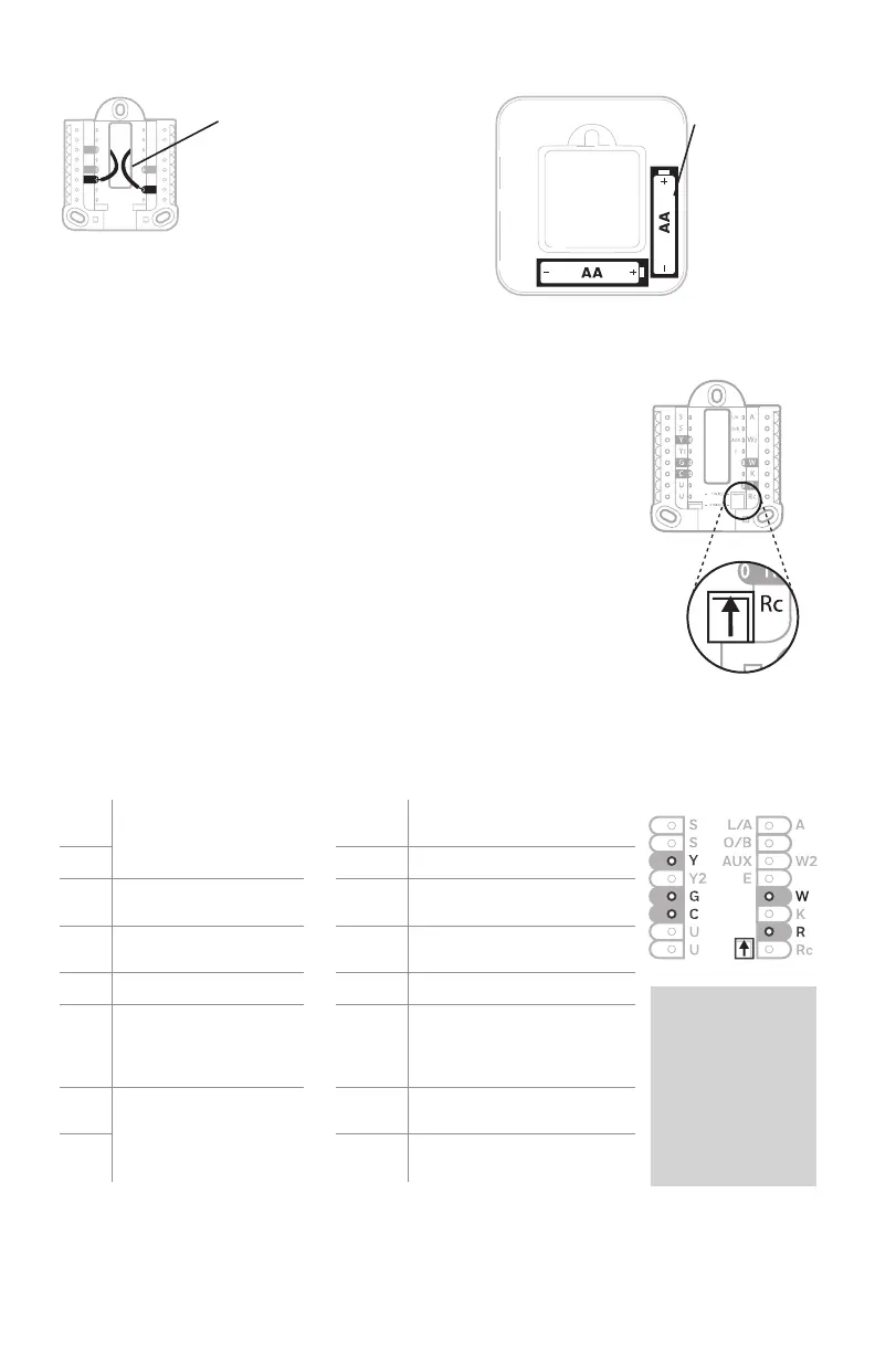
Set R Slider Tab.
• Use built-in jumper (R Slider Tab)
to differentiate between one or two
transformer systems.
• If there is only one R wire, and it is
connected to the R, Rc, or RH terminal, set
the slider to the up position (1 wire).
• If there is one wire connected to the R
terminal and one wire connected to the Rc
terminal, set the slider to the down position
(2 wires).
NOTE: Slider Tabs for U terminals should be
left in place for T4 Pro models.
Setting Slider Tabs
Insert R and C wires into
designated terminals
for primary AC power (C
terminal is optional if
batteries are installed,
but it is recommended).
Remove wires by
depressing the terminal
tabs.
Insert AA
batteries for
primary or
backup power.
R/Rc Slider Tab
(built-in jumper)
UWP Mounting System
 Loading...