14
EN1R--9161 0006R10--NE
Length ignition cable
0.5 m max.
Length of wiring for external components
1mmax.
Remark
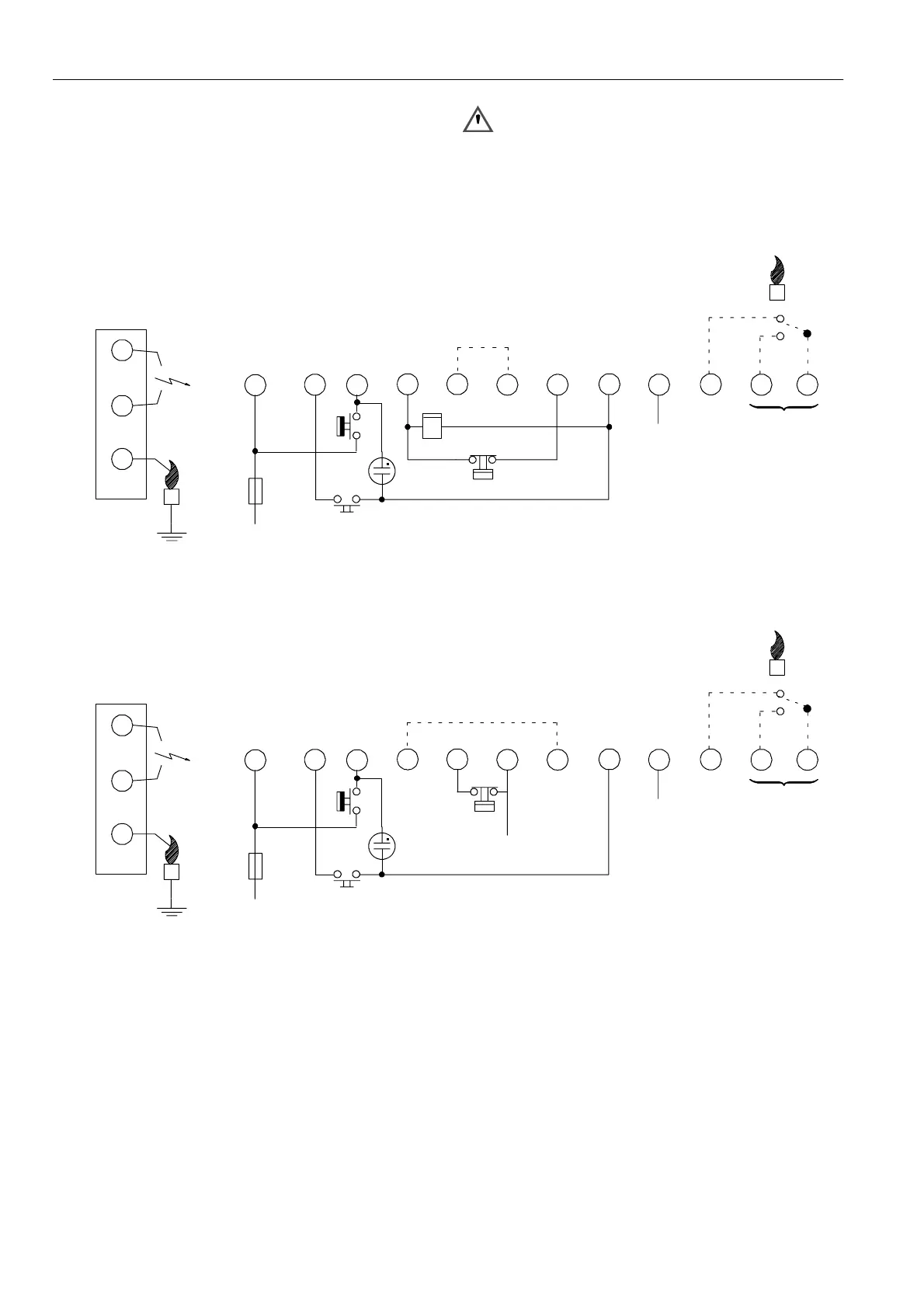
Optional integrated flame relay available with safe separation
or opto coupler with safe separation.
N.C. contact of flame relay has no safe separation.
WARNING
Opto coupler interface needs a debounce time > 20
ms in order to prevent noise caused by transients on
mains.
9
8
65
L
10
12
N
712
3
Optional
411
RS
Side connections *
LM -- Limiter
RS -- Res et s witch
h -- Hour counter
* See page 16. fig. 28.
** See page 10 fig. 17.
h and RS and alarm are optional
Optional **
h
LM
Fig. 22. Connection diagram S4565AD and BD “2000 “series
9
8
65
L
10
12
N
712
3
Optional
411
RS
Side connections *
LM -- Limiter
RS -- Res et s witch
* See page 16. fig. 28.
** See page 10 fig. 17.
RS and alarm are optional
Optional **
LM
LM output
Fig. 23. Connection diagram S4565AD and BD “2000 “series (optional )

 Loading...