16
EN1R--9161 0006R10--NE
9
8
65
N
10
12
712
3
411
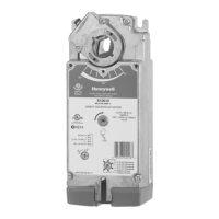
Side connections
Not
used
L
valves
L
ignition
Void
Fig. 27. Connection diagram S4565SD “2000” series
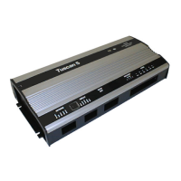
Side connections
Fig. 28. Alternative side connection if sparking to ground
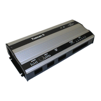
Side connection
Fig. 29. Alternative side connection in case of single rod
SYSTEM OPERATION
General
The S4565AD, BD, CD, DD, PD, QD, RD, TD ignition control
can provide both closed--loop sparking and sparking to
ground.
The S4565SD ignition circuit and rectifier provides
closed--loop sparking.
Lock- out reset
The S4565 can be is reset by either depressing the
internal/external reset button (suffix AD, BD, CD and DD) or
by interrupting the permanent life (suffix PD, QD, RD and TD).
NOTE 9.: If during normal use the reset button is pressed,
the gas valves close and the S4565 starts a new
sequence after releasing the reset button.
Suffix AD and PD (see fig. 30.)
When there is a call for heat a self check period (T
c
)plus
waiting period (T
w
) elapse before the built--in igniter and gas
valve are switched on.
The ignition spark ignites gas and resulting flame is detected
by the flame rod.
After flame establishment a predetermined, extended ignition
time can be included.
If flame is not established within the safety time (T
s
), the
S4565 ignition control locks out.
If the flame is lost during normal run, the S4565 ignition
control repeats start sequence.
Suffix BD and QD (see fig. 31.)
As AD and PD except flame relay contact or opto is activated
after flame detection.
NOTE 10.: The hour counter is energized when the valve is
energized. It can be used as an output signal.
Suffix CD and RD (see fig. 32.)
When there is a call for heat, self check period (T
c
)plus
waiting period (T
w
) elapse when the air proving switch is in the
no air position.
After T
c
+T
w
the fan starts running.
When sufficient air flow is proven by the air proving switch, the
built--in igniter and gas valve are switched on.
The ignition spark ignites gas and resulting flame is detected
by the flame rod.
After flame establishment a predetermined, extended ignition
time can be included.
If flame is not established within the safety time (T
s
), the
S4565 ignition control locks out.
If the flame is lost during normal run, the S4565 ignition
control repeats start sequence.

 Loading...