5
EN1R--9161 0006R10--NE
Ignition
Spark voltage: > 12 kV at 40 pF load
Repetition rate: 2.5 ... 60 Hz (depending on O.S. number)
Max spark gap: 3.5 mm
Leng th flame sensing cable
1mmax.
Length ignition cable
0.5 m max.
Length of wiring for external components
1mmax.
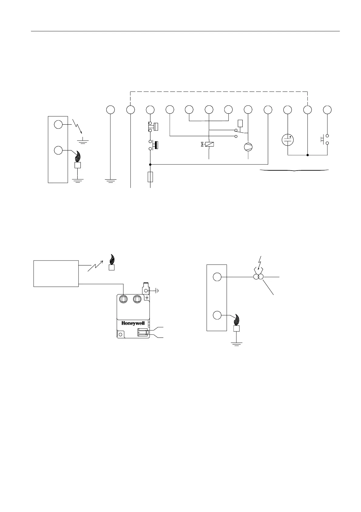
P -- Air proving switch
LM -- Limiter
RS -- Reset switch
* See note 5.
** Alternative side connection for models with combined flame
detection/high voltage. See page 5 fig. 6.
P
10
3
7
1
L
11
N
Side connections**
8
24
569
LM
RS
12
Optional
*¯
N
LPG
¯
N
¯
Fig. 5. Connection diagram S4565C, D, R, T
Special applications
input
ignition control
N
L
21
Ph1
Ph2
AT7030
Fig. 6. Alte rnative side connection for models with
combined flamedetection/high voltage.
Side connection
230 Vac
N
Ignition transformer
Fig. 7. Alternative side connection for models with flame
sense input + 230 Vac output for external ignition
transformer

 Loading...