6
EN1R--9161 0006R10--NE
SYSTEM OPERATION
General
Lock- out reset
The S4565 can be reset by either depressing the
internal/external reset button (suffix C and D) or by
inte rrupting the permanent life (suffix R and T).
NOTE 4.: If during normal use the reset button is pressed,
he gas valves close and the S4565 ignition control
starts a new sequence after releasing the reset
button.
NOTE 5.: If permanent alarm output:
neon indicator with integral resistor >150 kτ
Εmax 1 mA)
Suffix C and R (see fig. 8.)
When there is a call for heat the fan starts running through the
no air position of the air proving switch.
If an external LPG valve is connected, this will be energized.
When sufficient air flow is proven by the air proving switch, a
self check period (T
c
) and prepurge period (T
p)
elapse before
the gas valve and built--in ignition or external ignition
transformer (optional) are switched on.
The ignition spark ignites gas and resulting flame is detected
by the flame rod.
Internal or external ignition is switched off.
After flame establishment a predetermined, extended ignition
time can be included.
If flame is not established within the safety time (T
s
), the
S4565 ignition control locks out.
If the flame is lost during normal run, the S4565 ignition
control repeats the start sequence with prepurge.
If no air is proven by the air proving switch within the prepurge
time (T
p
), the ignition control stays in waiting mode with fan
running.
Suffix D and T (see fig. 9.)
When there is a call for heat the fan starts running through the
no air position of the air proving switch.
If an external LPG valve is connected, this will be energized.
When sufficient air flow is proven by the air proving switch, a
self check period (T
c
) and prepurge period (T
p)
elapses before
the pilot gas valve and built--in ignition or external ignition
transformer (optional) are switched on.
The ignition spark ignites pilot gas and resulting flame is
detected by the flame rod.
Internal or external ignition is switched off.
After flame establishment a predetermined, extended ignition
time can be included and flame establishment and the main
valve is switched on.
If flame is not established within the safety time (T
s
), the
S4565 ignition control locks out.
If the flame is lost during normal run, the S4565 ignition
control repeats start sequence at prepurge.
If no air is proven by the air proving switch within the prepurge
time (T
p
), the ignition control stays in waiting mode with fan
running.
WARNING
Do not interchange air proving switch wiring in order to
prevent malfunctioning
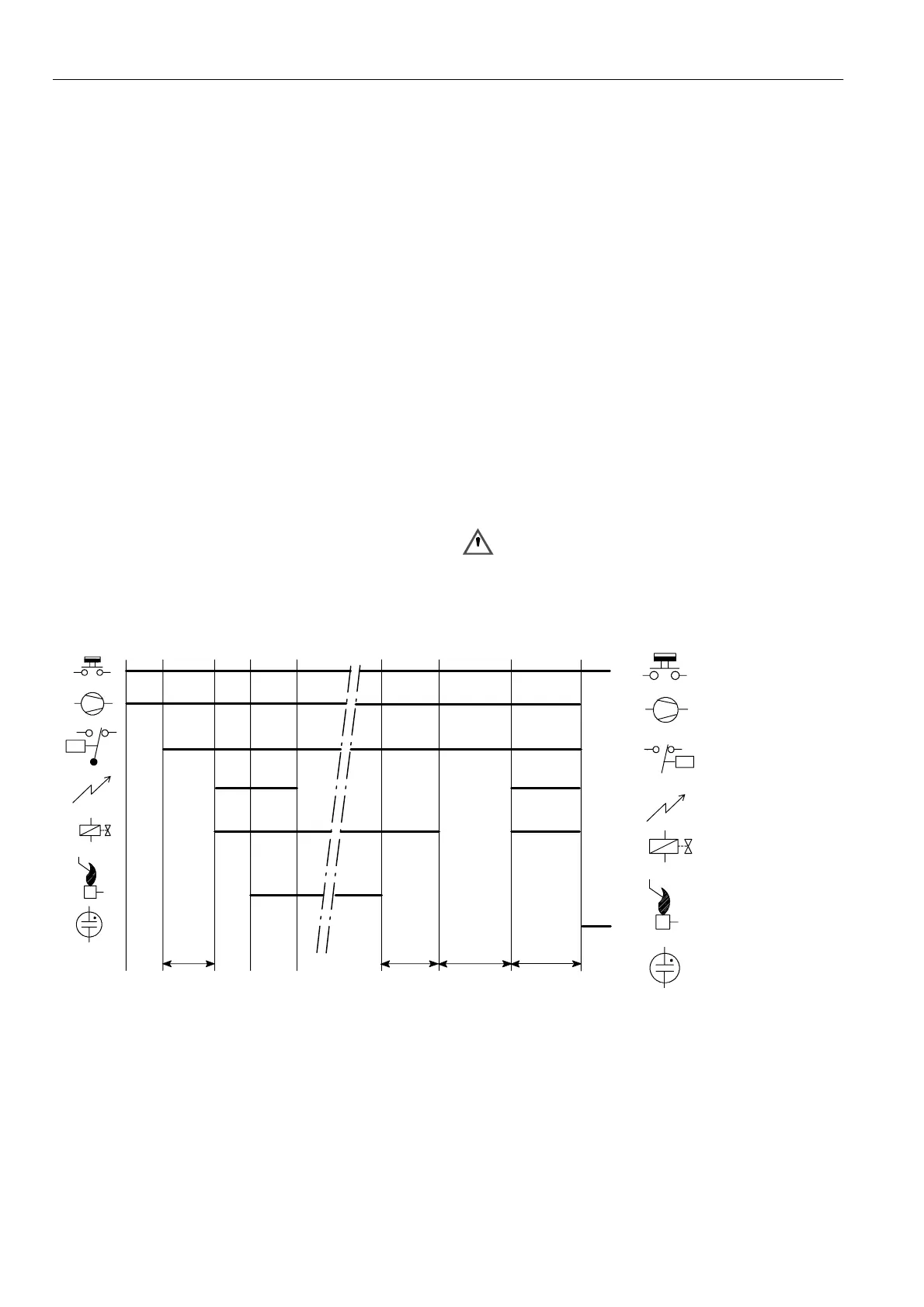
T
c+
T
p
P
P
¯
Thermostat
Fan
Air proving switch
Ignition
Main v a lve
Flame rod
Legend
T
s
Alarm
T
c+
T
p
T
FR
Fig. 8. Functional diagram S4565C, R

 Loading...