RM7888A 7800 SERIES RELAY MODULE
32-00214—01 14
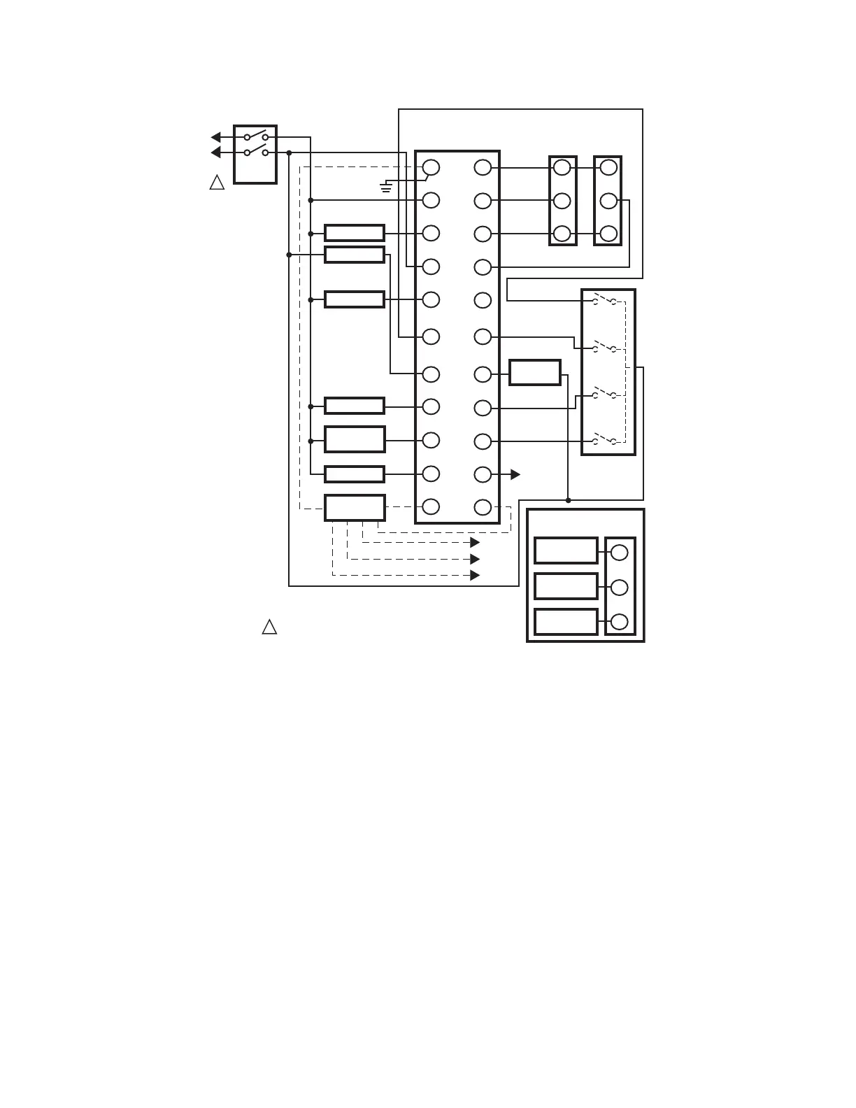
Fig. 11. RM7888A wiring diagram.
4. Recommended wire size and type:
a. Use 14, 16, or 18 AWG copper conductor
(TTW60C or THW75C or THHN90C) 600 volt
insulation wire for all line voltage terminals. For
high temperature installations, use wire selected
for a temperature rating above the maximum
operating temperature. All leadwires must be
moisture resistant.
b. Keyboard Display Module—For communications
purposes, use an unshielded 3-wire twisted
cable if the leadwire run and noise conditions
permit; however, some installations may need up
to five wires; three for communications and two
for remote reset (either in a single cable or sepa-
rate cables for communications or remote reset)
or use Belden 8771 shielded cable or equivalent.
The Keyboard Display Module, DATA CONTROL-
BUS MODULE™ (for remote mounting or com-
munications) or Modbus Module must be wired
in a daisy-chain configuration, 1(a)-1(a), 2(b)-
2(b), 3(c)- 3(c)). The order of interconnection of
all the devices is not important. Be aware that
modules on the closest and farthest end of the
daisy chain configuration require a 120-ohm
(1/4 watt minimum) resistor termination across
terminals 1 and 2 of the electrical connectors for
connections over 100 feet [30 meters].
c. DATA CONTROLBUS or MODBUS MODULE™—
For communications purposes, use an
unshielded 3-wire twisted cable if the leadwire
run and noise conditions permit; however, some
installations may need up to five wires; three for
communications and two for remote rest (either
in a single cable or separate cables for communi-
cations or remote reset) or use Belden 8771
shielded cable or equivalent. The Keyboard Dis-
play Module, DATA CONTROLBUS MODULE™
(for remote mounting or communications) or
Modbus Module must be wired in a daisy-chain
configuration, 1(a)-1(a), 2(b)-2(b),3(c)-3(c)). The
order of interconnection of all the devices is not
important. Be aware that modules on the closest
and farthest end of the daisy chain configuration
require a 120-ohm (1/4 watt minimum) resistor
termination across terminals 1 and 2 of the elec-
trical connectors for connections over 100 feet
[30 meters].
M9495A
G
L2
3
4
5
6
7
8
9
10
F
(L1)
13
14
15
16
17
18
19
20
21
22
12
MASTER
SWITCH
LIMITS
SPECIAL
FUNCTION 1
SPECIAL
FUNCTION 2
SPECIAL
FUNCTION 3
SPECIAL
FUNCTION 4
FLAME
INDICATION
MAIN FUEL
VALVE(S)
120V ALARM
PILOT
FLAME
DETECTOR
120V POWER SUPPLY. PROVIDE DISCONNECT MEANS
AND OVERLOAD PROTECTION AS REQUIRED.
L1
(HOT)
L2
1
L2
L1
L2
1
Q7800 SUBBASE
HIGH
FIRE
COMMON
LOW
FIRE
MODULATE
B
R
W
SERIES 90
FIRING
RATE
MOTOR
B
R
W
SERIES 90
CONTROLLER
LOW FIRE
SWITCH
IGNITION
AIR VALVE
EXTERNAL
CONTROLLER
FOR DIRECT SPARK
IGNITION (OIL OR GAS)
IGNITION
2ND STAGE
FUEL VALVE
1ST STAGE
FUEL VALVE
8
9
10

 Loading...


