RM7888A 7800 SERIES RELAY MODULE
32-00214—01 30
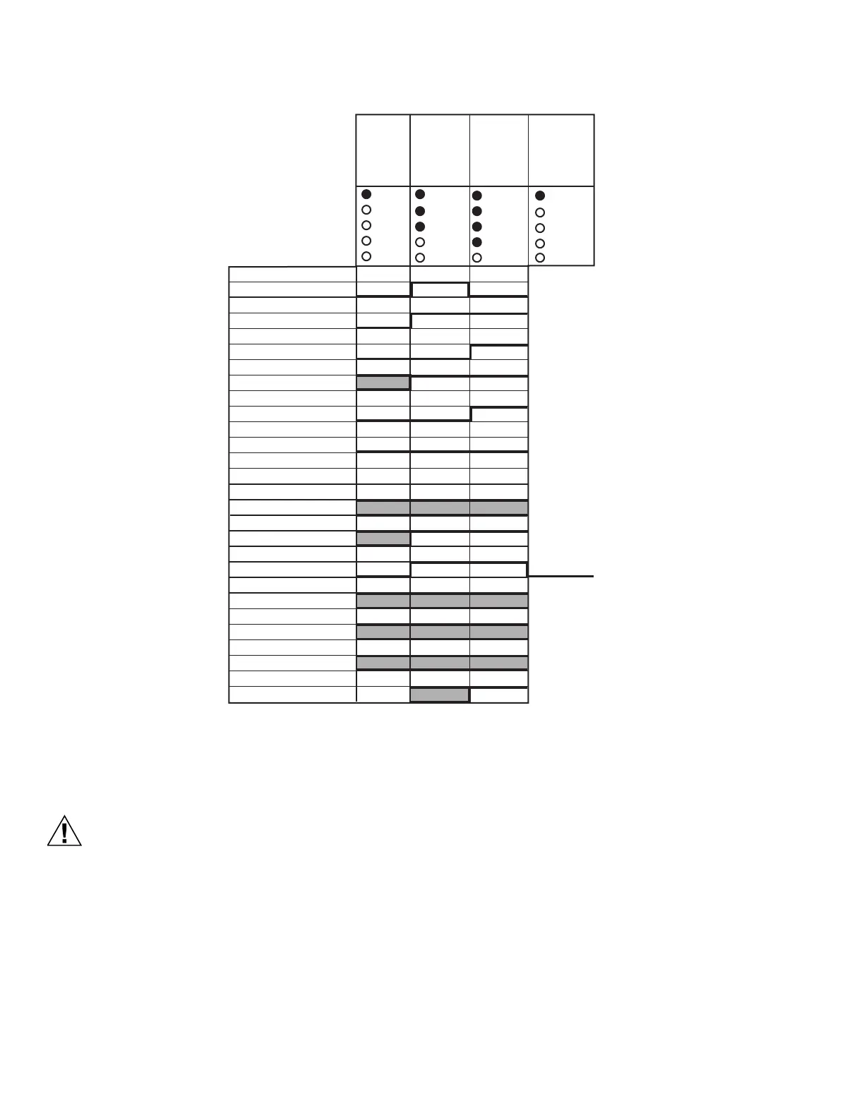
Fig. 24. DSI On/Off Stepfire sequence diagram.
STATIC CHECKOUT
1. Use extreme care while testing the system. Line
voltage is present on most terminal connections
when power is on.
2. Open the master switch before installing or remov-
ing a jumper on the subbase.
3. Before continuing to the next test, be sure to
remove the test jumper(s) used in the previous
tests.
4. Replace all limits and interlocks not operating
properly. Do not bypass limits and interlocks.
5. Close all manual fuel shutoff valve(s) before start-
ing these tests.
After checking all wiring, perform this checkout before
installing the RM7888A on the subbase. These tests
verifies that the Q7800 Wiring Subbase is wired correctly,
and that the external controllers, limits, interlocks,
actuators, valves, transformers, motors and other devices
are operating properly.
NOTE: Do not perform a dielectric test with the
RM7888A installed. Internal surge protectors will
break down and conduct a current. This could
cause the RM7888A to fail the dielectric test or
possibly destroy the internal lightning and high
current protection.
INPUT &
OUTPUT
SIGNALS
POWER
PILOT
FLAME
MAIN MAIN
ALARM
STANDBY
STANDBY-
PURGE
POWERPOWER
IGNITION- T10
PILOT- T8
MAIN- T9
AIR VALVE- T5
FLAME PROVEN- T21
ALARM- T3
MOTOR POSITION- T12-T15 L/H/MOD MOD
TO STANDBY
MOD
@ LOW FIRE INPUT- T18
LIMITS COMPLETE- T7
SF1 SPECIAL FUNCTION- T6
SF2 SPECIAL FUNCTION- T17
SF3 SPECIAL FUNCTION- T19
SF4 SPECIAL FUNCTION- T20
FLAME SENSED
POWER
PILOT
FLAME
PILOT
FLAME
POWER
M9492B
5 TO
INFINITE
SECONDS
OFF/ON
STEPFIRE-
PART 1*
OFF/ON
STEPFIRE-
PART 2
*RM7888A1001 AND A1019 ARE 4 SECONDS. RM7888A1027 IS 10 SECONDS.

 Loading...


