RM7888A 7800 SERIES RELAY MODULE
13 32-00214—01
4. Mount the subbase securely using four No. 6 screws.
NOTE: You might receive an error code 101 (via KDM) if
one of the following conditions exist:
a. The screws securing the relay to the subbase are
not tight enough, re-tighten to insure there is no
gap between the relay and the subbase.
b. If you attempt to place a 2000 series relay on a
non-compatible 1000 series subbase, this indi-
cates that you must:
• Change out the subbase to a Q7800A2003/U
or Q7800A2005/U
• Choose a compatible 1000 series relay
modulebase to a Q7800A2003/U or
Q7800A2005/U
WIRING
1.
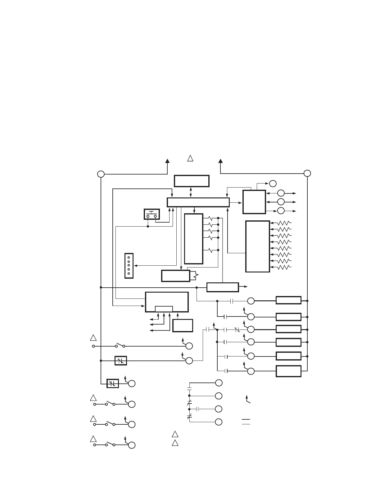
a. For the internal block diagram of the RM7888A,
see Fig. 10.
b. For proper subbase wiring, refer to Fig. 11.
c. For proper remote wiring of the Keyboard Display
Module; refer to the Specifications for the Key-
board Display Module (65-0090), or Extension
Cable Assembly (65-0131).
2. Disconnect the power supply from the main discon-
nect before beginning installation to prevent electri-
cal shock and equipment damage. More than one
disconnect may be involved.
3. All wiring must comply with all appropriate electrical
codes, ordinances and regulations. Wiring, where
required, must comply with NEC Class 1 wiring.
Fig. 10. RM7888A internal block diagram.
CONFIGURATION
JUMPERS
MICROCOMPUTER
RESET
PUSHBUTTON
STATUS LEDs
SAFETY RELAY
CIRCUIT
POWER SUPPLY
OPTIONAL
KEYBOARD
DISPLAY MODULE
PLUG-IN
FLAME
AMPLIFIER
RELAY
DRIVE
CIRCUIT
CONTROL
POWER
TEST
JACK
L2
REMOTE
RESET
DDL
DDL
COMMUNICATIONS
INDICATES FEEDBACK SENSING
OF RELAY CONTACT
AND LINE VOLT INPUTS
FIELD WIRING
INTERNAL WIRING
IGNITION
AIRVALVE
MAIN VALVE
1K
RELAY
STATUS
FEEDBACK
AND LINE
VOLTAGE
INPUTS
1K1
5K1
120 Vac
FLAME SIGNAL
TEST
PROVIDE DISCONNECT MEANS AND OVERLOAD PROTECTION AS REQUIRED.
120 VAC INPUT FROM SYSTEM MASTER CONTROLLER REFER TO
TABLE 1 AND FIGURE 8.
RS485
1
2
3
L1 (HOT)
L2
4
6
7
6K1
4K1
2K2
5
3
10
8
9
7K
5K
4K
3K
2K
F
G
22
1
FLAME
PROVEN
7K1
21
1
2
2
2
2
2
M9496D
LIMITS COMPLETE
ALARM
PILOT
SPECIAL FUNCTION 1
17
18
LOW FIRE
SWITCH
SPECIAL
FUNCTION 2
SPECIAL
FUNCTION 3
SPECIAL
FUNCTION 4
19
20
8K1
HIGH FIRE
12
COMMON
13
MODULATE
15
LOW FIRE
14
9K1
8K2
9K2
5
2K2
3K1

 Loading...


