RM7888A 7800 SERIES RELAY MODULE
32-00214—01 32
CHECKOUT
Do not allow fuel to accumulate in the
combustion chamber. If fuel is allowed to enter
the chamber for longer than a few seconds
without igniting, an explosive mixture could
result. It is recommended that the trial for pilot
be limited to ten seconds, and the attempt to
light the main burner be limited to two seconds
from the time the fuel has reached the burner
nozzle. In any case, do not exceed the nominal
lightoff time specified by the equipment
manufacturer. Close the manual fuel shutoff
valve(s) if the flame is not burning at the end of
the specified time.
1. Use extreme care while testing the system. Line
voltage is present on most terminal connections
when power is on.
2. Open the master switch before removing or install-
ing the RM7888A.
3. Make sure all manual fuel shutoff valve(s) are
closed before starting the initial lightoff check and
the Pilot Turndown tests.
4. Do not put the system in service until you have
satisfactorily completed all applicable tests in this
section and any others required by the equipment
manufacturer.
If an RM7888A is replaced with a lower
functioning 7800 SERIES Relay Module, the
burner will not sequence unless wiring changes
are made.
IMPORTANT
1. If the system fails to perform properly, refer to the
Troubleshooting section and 7800 SERIES System
Annunciation and Troubleshooting, form 65-0229
2. Repeat ALL required Checkout tests after all
adjustments are made. ALL tests must be satisfied
with the flame detector(s) in its FINAL position.
Make sure all manual fuel shutoff valves are closed.
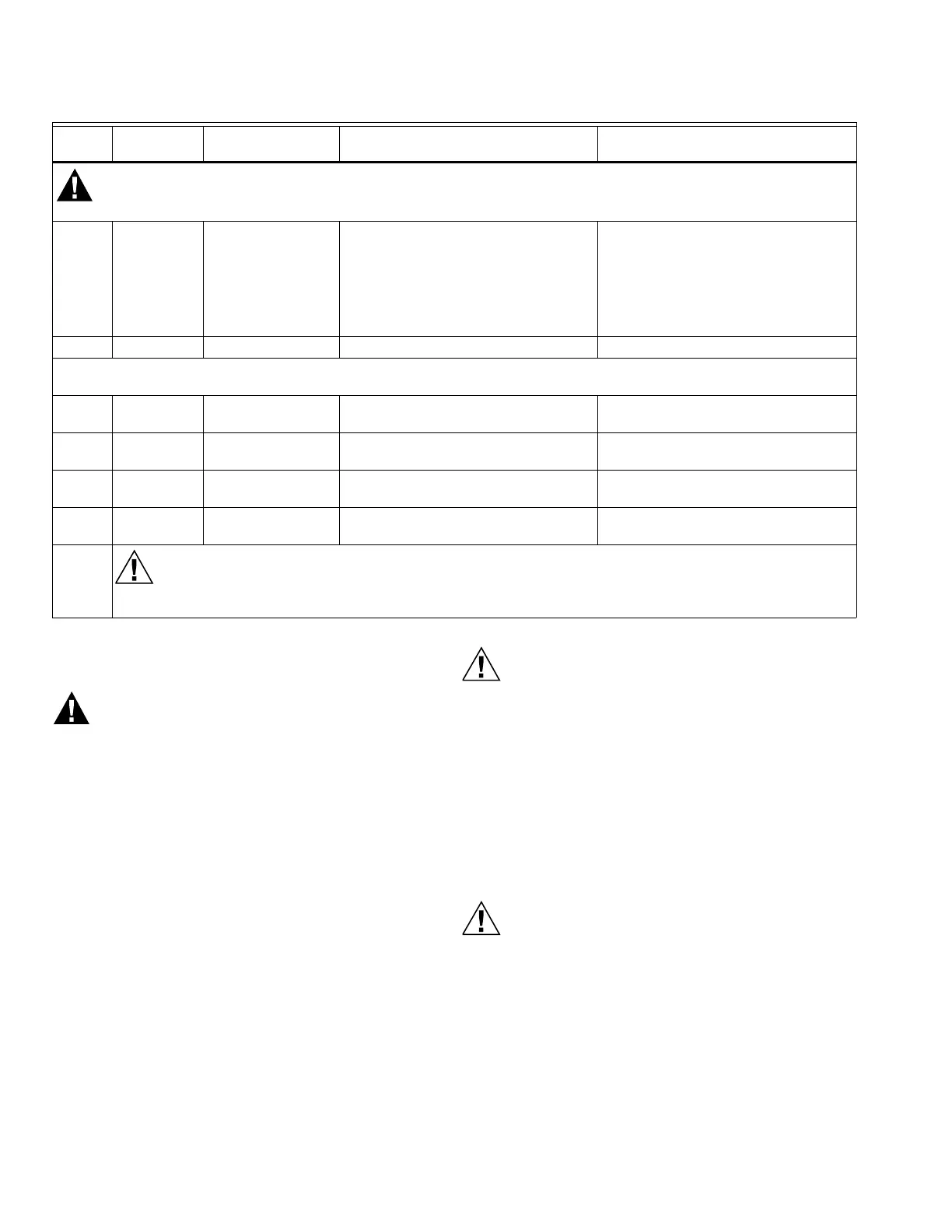
10 15-13 — 1. If modulation is used, raise set-
point of series 90 controller— fir-
ing rate motor should drive
toward open.
2. Lower set point of series 90 con-
troller—firing rate motor should
drive toward closed.
1. Series 90 Controller.
2. Firing rate motor and trans-
former.
11 4-21 — 1. Flame Proven circuit.
* Apply 120 Vac power to the special function inputs from the external controller/device one at a time (in sequence) and
perform tests 12 through 15.
12 — 1. 6-L2
2. 17, 19, 20-L2
1. Special Function 1 circuit.
13 — 1. 17-L2
2. 6, 19, 20-L2
1. Special Function 2 circuit.
14 — 1. 19-L2
2. 6, 17, 20-L2
1. Special Function 3 circuit.
15 — 1. 20-L2
1. 6, 17, 19-L2
1. Special Function 4 circuit.
Final
On completing these tests, open the master switch and remove all test jumpers from the subbase
terminals. Also remove bypass jumpers from the low fuel pressure limits (if used).
Table 10. Static Checkout. (Continued)
Test
No.
Test
Jumpers Voltmeter Normal Operation
If Operation Is Abnormal, Check The
Items Listed Below

 Loading...


