RM7888A 7800 SERIES RELAY MODULE
33 32-00214—01
Equipment Recommended
Volt-ohmmeter (1 Megohm/volt minimum sensitivity)
with:
• 0-300 Vac capability.
• 0-6000 ohm capability.
• 0-10 Vdc capability.
Checkout Summary
• Preliminary inspection—all installations.
• Flame signal measurement—all installations.
• Initial lightoff check for proved pilot—all installations
using a pilot.
• Initial lightoff check for direct spark ignition of oil— all
burners using DSI.
• Pilot turndown test—all installations using a pilot.
• Hot refractory saturation test—all installations using
Infrared (lead sulfide) Flame Detectors.
• Hot refractory hold-in test—all installations.
• Ignition interference test—all installations using flame
rods.
• Ignition spark pickup—all installations using Ultraviolet
Flame Detectors.
• Response to other ultraviolet sources—all installations
using Ultraviolet Flame Detectors.
• Flame signal with hot combustion chamber—all
installations.
• Safety shutdown tests—all installations.
See Figs. 10 and 11 or Q7800 Specifications for terminal
locations.
Preliminary Inspection
Perform the following inspections to avoid common
problems. Make certain that:
1. Wiring connections are correct and all terminal
screws are tight.
2. Flame detector(s) is clean, installed and positioned
properly. Consult the applicable Instructions.
3. Correct combination of amplifier and flame detec-
tor(s) is used. See Table 4 in the Specifications sec-
tion.
4. Plug-in amplifier is securely in place.
5. Burner is completely installed and ready to fire; con-
sult equipment manufacturer instructions. Fuel
lines are purged of air.
6. Combustion chamber and flues are clear of fuel and
fuel vapor.
7. Power is connected to the system disconnect switch
(master switch).
8. Lockout is reset (push in reset button), only if the
RM7888A is powered.
9. System is in the Standby condition. POWER LED is
energized.
10. All limits and interlocks are reset.
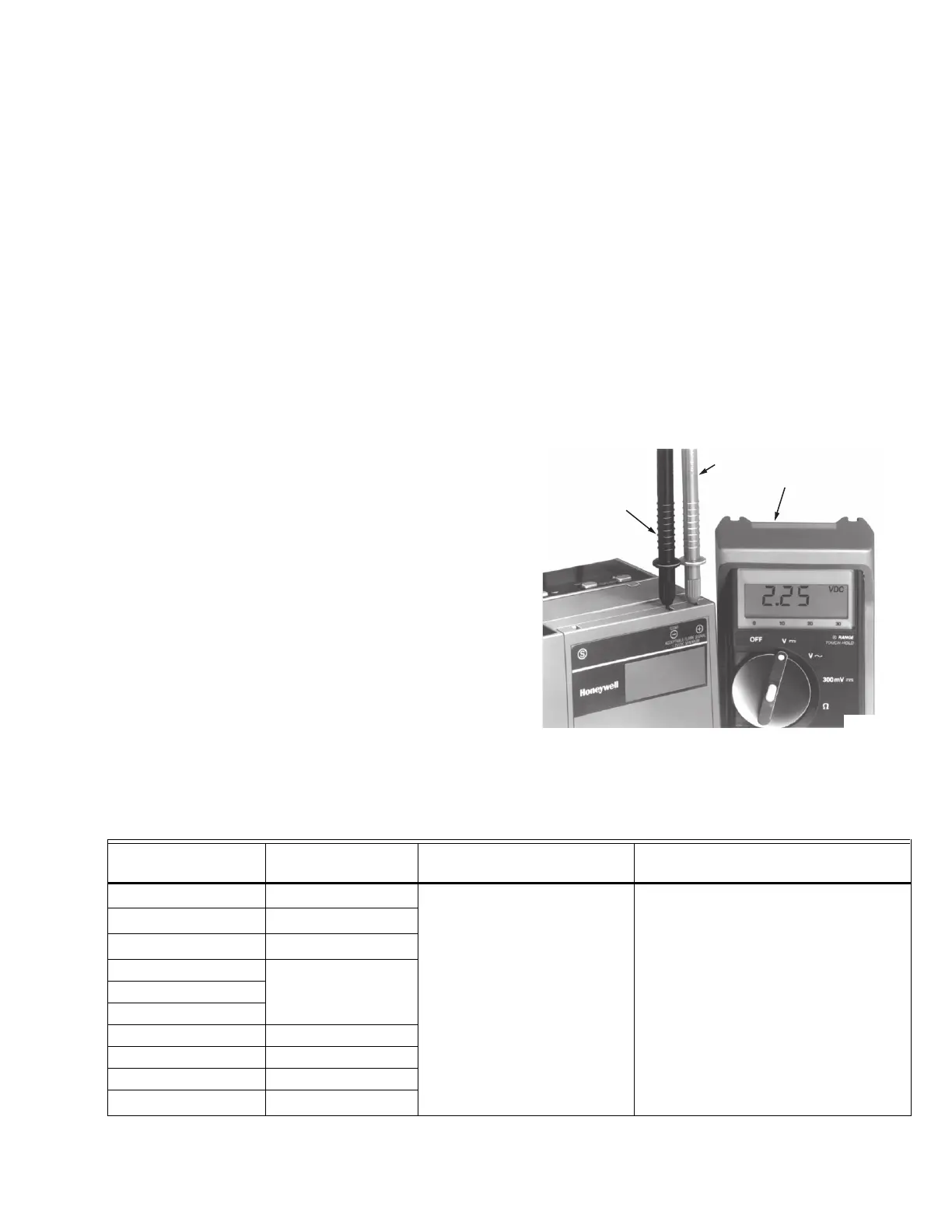
Flame Signal Measurement (Table
11 and Fig. 25)
Fig. 25. Flame signal measurement.
Table 11. Flame Signal.
NEGATIVE (–)
METER LEAD
POSITIVE (+)
METER LEAD
ONE MEGOHM/VOLT
METER
M7382A
Flame Detector Signal Amplifier
Minimum Acceptable Steady
dc Voltage
a
Maximum Expected dc Voltage
Flame Rod C7012A,C
R7847A,B
c
1.25 Vdc 5.0 Vdc at Keyboard Display Module
or 5.0 Vdc at a 1 Megohm/volt meter
C7012E,F
R7847C
b
C7915A
R7852A,B
c
C7027A
R7849A,B
c
C7035A
C7044A
C7061 R7861
C7076A,D R7886A
C7961 R7851C
C7927, C7961
R7851B
c

 Loading...


