RM7888A 7800 SERIES RELAY MODULE
31 32-00214—01
Equipment Recomended
• Voltmeter 1Mohm/volt minimum sensitivity set on the
0-300 Vac scale.
• Two jumper wires; 14 AWG wire, insulated, 12 inches
(304.8 mm) long, with insulated alligator clips at both
ends.
NOTE: An ammeter can replace one jumper wire so the
current draw of the loads (pilot valve, main valve
and ignition transformer) can be checked.
General Instructions
1. Perform all applicable tests listed in Static Checkout,
Table 10, in the order listed.
2. Make sure that all manual fuel shutoff valve(s) are
closed.
3. For each test, open the master switch and install the
jumper wire(s) between the subbase wiring termi-
nals listed in the Test Jumpers column.
4. Close the master switch before observing operation.
5. Read the voltage between the subbase wiring termi-
nals listed in the Voltmeter column.
6. If there is no voltage or the operation is abnormal,
check the circuits and external devices as described
in the last column.
7. Check all wiring for correct connections, tight termi-
nal screws, correct wire, and proper wiring tech-
niques. Replace all damaged or incorrectly sized
wires.
8. Replace faulty controllers, limits, interlocks, actua-
tors, valves, transformers, motors and other devices
as required.
9. Obtain normal operation for each required test
before continuing the checkout.
10. After completing each test, be sure to remove the
test jumper(s).
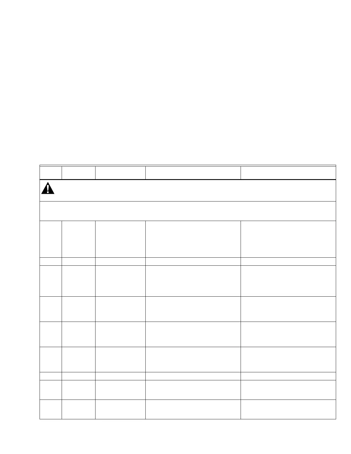
Table 10. Static Checkout.
Test
No.
Test
Jumpers Voltmeter Normal Operation
If Operation Is Abnormal, Check The
Items Listed Below
Make sure all manual fuel shutoff valves are closed.
IMPORTANT
Low fuel pressure limits, if used, could be open. Bypass them with jumpers for the remaining Static Tests (if
required).
1 None 4-L2 Line voltage at terminal 4. 1. Master switch.
2. Power connected to the master
switch.
3. Overload protection (fuse, circuit
breaker) has not opened the
power line.
2 None 7-L2 Line voltage at terminal 7. 1. Limits.
34-5 1. Air Valve starts. 1. Air Valve circuit.
a. Manual switch of Air Valve.
b. Air Valve power supply, over-
load protection, and starter.
c. Air Valve.
4 4-10 — Ignition spark 1. Watch for spark or listen for
buzz.
a. Ignition electrodes are clean.
b. Ignition transformer.
54-8 — 1. Automatic pilot valve opens.
NOTE: Refer to wiring diagram of
system being tested.
1. Listen for click or feel head of
valve for activation.
a. Actuator if used.
b. Pilot valve.
6 4-9 — Automatic main fuel valve(s) opens. 1. Listen for and observe operation
of the main fuel valve(s) and
actuator(s).
2. Valve(s) and actuator(s).
7 4 -3 — Alarm (if used) turns on. 1. Alarm
84-5 and
12-13
18-L2 Firing rate motor drives open; zero
volts at terminal 18 after motor starts
driving open.
1. Low Fire Start Switch.
2. Firing rate motor and trans-
former.
94-5 and
14-13
18-L2 Firing rate motor drives closed; line
voltage at terminal 18 after motor is in
Low Fire position.
1. Low Fire Start Switch.
2. Firing rate motor and trans-
former.

 Loading...


