RM7888A 7800 SERIES RELAY MODULE
32-00214—01 20
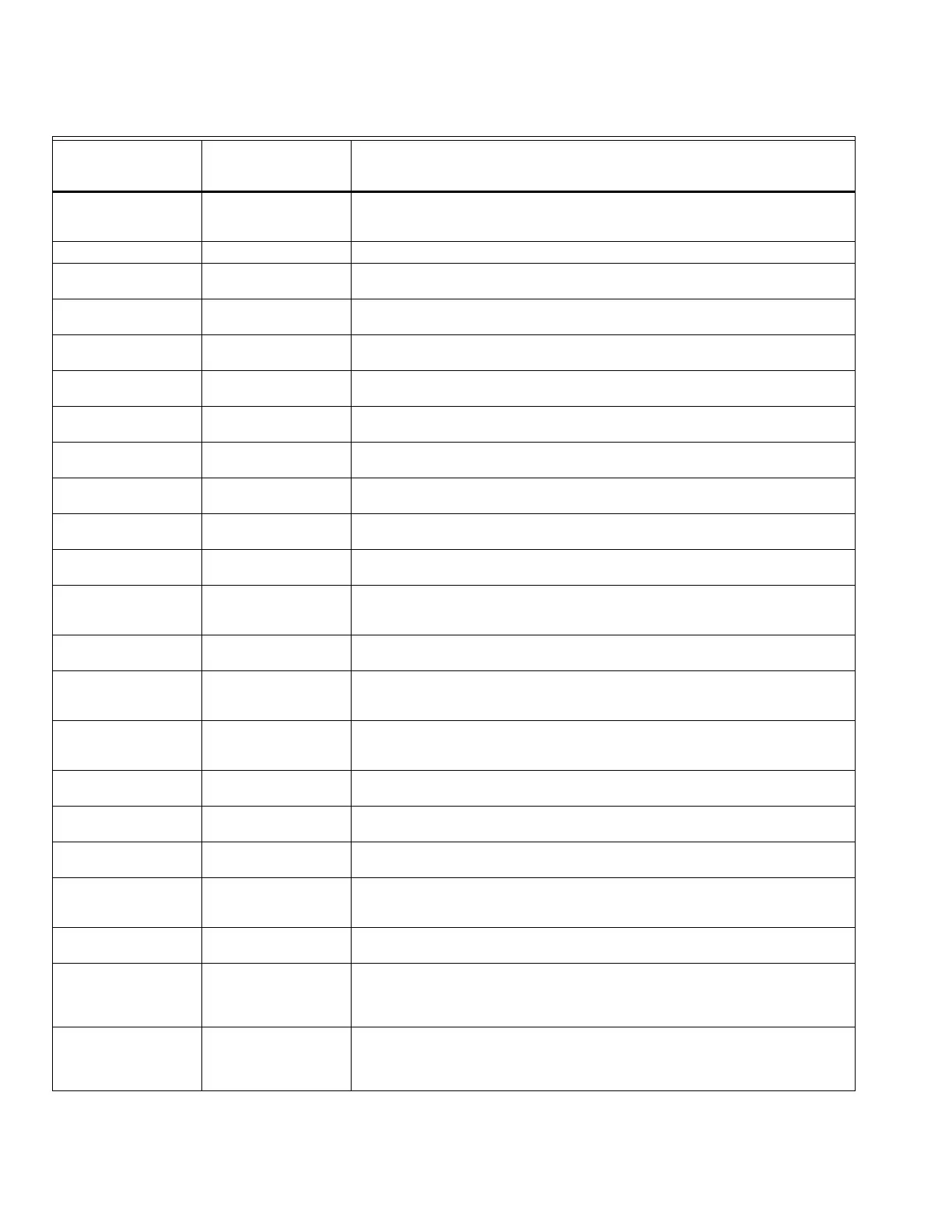
Table 7. Pilot Configuration Operation Sequence States.
Pilot Configuration
State Name
S7800 Keyboard
Display Module
Displayed Text Purpose of State
Initiate (See below) The Initiate state allows the relay module to complete initialization after a
power-up or whenever a problem that would prevent normal operation (such
as an ac line problem), the Initiate state is entered.
Initiate INITIATE mm:ss Displayed during timed portion of the Initiate state.
Initiate INITIATE HOLD: AC
(AC Freq/Noise)
Displayed during Initiate state if the ac frequency is low or noise is present.
Initiate INITIATE HOLD: AC
(AC Line Dropout)
Displayed during Initiate state if the ac line power was lost.
Initiate INITIATE HOLD: AC
(AC Frequency)
Displayed during Initiate state if the ac frequency is high.
Initiate INITIATE HOLD: AC
(Low Line Voltage)
Displayed during Initiate state if the ac line voltage is low.
Off STANDBY Remaining idle until valid input(s) are received. All safety loads are
commanded off.
— STANDBY HOLD: F/G
(Flame Detected)
Displayed when a flame is detected.
— STANDBY HOLD: T7
(Lockout ILK)
Displayed when a call for operation is active and the Limits Complete signal
is off.
PURGE HOLD: T18
(Low Fire Switch)
Displayed when a call for operation is active and the Low Fire Switch signal
is off.
Purge PURGE 01:00 Purge at high fire. All safety loads are commanded off. Display indicates
Purge type 1 = Purge.
Control Cool PURGE 02:00 Purge at the motor position commanded by the modulating control. All
safety loads are commanded off. Display indicates Purge type 2 = Control
Cool.
Low Combustion Air
Only
PURGE 03:00 Purge at low fire. All safety loads are commanded off. Display indicates
Purge type 3 = Low Combustion Air Only.
Pilot Ignition PILOT IGN mm:ss Establish a pilot flame. Display shows state and elapsed time. At end of Pilot
Ignition timed state, timer will stop and display will show final time while a
hold exists.
Main Train Fuel On MAIN IGN 00:00 Allow for main valve operators to be placed into the normal operating
condition. Display shows state with zero elapsed time while waiting for a
hold condition(s).
Burner Fuel Valve
Open (Pilot Timeout)
MAIN IGN 00:ss Establish a main flame and drop the pilot flame. Display will show MFEP
state elapsed time.
Release to
Modulation
RUN Allow normal operation to take place where a modulating control provides
the motor position signal.
— RUN When special function input terminal 20 is off, relay module will command a
Low Fire motor position.
@Low 10 Sec RUN When the Low Fire input becomes energized for a continuous time period of
10 seconds, the sequence will leave the Release to Modulation state and
proceed to the Pilot Relight state (PV Return sequence only).
Pilot Relight PVHOLD IGN 00:ss Re-establish the pilot flame and drop the main flame. Display indicates
elapsed time in this timed state (PV Return sequence only).
Low Off 5 Sec. PVHOLD IGN 01:00 Wait for the Low Fire input signal to become de-energized for a continuous
period of five seconds and then proceed to the Main Train Fuel On state
after driving back to the Low Fire position. Display indicates that sequence
is in Pilot Hold State type 1 = Waiting for Low Off 5 Sec.
Drive to Low PVHOLD IGN 02:00 Commands the low fire motor position and waits until the Low Fire input
becomes energized before proceeding to the Main Train Fuel On state.
Display indicates that sequence is in Pilot Hold State type 2 = Waiting for
Low Fire On.

 Loading...


