Do you have a question about the Honeywell 800 Series and is the answer not in the manual?
| Brand | Honeywell |
|---|---|
| Model | 800 Series |
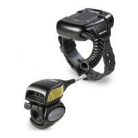
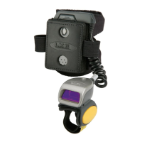
| Category | Barcode Reader |
| Language | English |
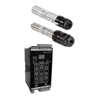
Details the single-channel, fail-safe flame monitoring system using 700ACSP/700DCSP with S70X/S80X viewing heads.
Highlights viewing head interchangeability and the availability of two signal processor models.
Details electrical, environmental, detector specs, optical properties, and cable for S70X/S80X viewing heads.
Provides electrical and output specifications for Model 700ACSP and 700DCSP signal processors.
Lists safety and regulatory approvals for S70X/S80X viewing heads and 700ACSP/700DCSP processors.
Provides essential instructions, warnings, and procedures for installing the signal processors and viewing heads.
Explains power and relay connections for 700ACSP and 700DCSP, including backup power.
Details terminal functions for viewing heads and describes C330S cable for new installations.
Covers explosion hazard warnings and procedures for installing cables in hazardous locations.
Provides step-by-step instructions for preparing the C330S cable for connection to the signal processor.
Discusses conduit sealing requirements for Class I, Division 2 hazardous locations.
Explains the function of green and orange LEDs on the viewing head connector for status and troubleshooting.
Details mounting block types, pressure ratings, and heat considerations for viewing heads.
Covers the importance of purge air for cooling and lens clarity, and vibration mitigation.
Provides guidance on aiming the viewing head for optimal flame detection and performance.
Lists various accessories like orifice disks, mounting blocks, and converters for system configuration.
Explains how IR detectors work, their response to flicker, and sighting for optimal performance.
Describes UV detector operation, spectral response, and suitability for various flame types.
Explains the self-check circuitry that ensures proper interaction between viewing head and processor.
Details how to adjust viewing head sighting for maximum signal and proper alignment.
Describes the user interface components: LEDs, display, and push buttons for operation and programming.
Details the specific functions of each push button for setup and operation.
Guides on adjusting IR/UV viewing head gain from 1 to 9 for optimal signal detection.
Explains how to set the Relay On threshold value based on flame signal counts.
Provides steps to test and resolve issues with background flame detection during operation.
Discusses X-ray radiation effects on IR sensors and conditions for system testing.
Explains how to set the Relay Off setpoint as a percentage of the Relay On setpoint.
Guides on setting the FFRT to 1, 2, or 3 seconds for flame failure detection.
Details how to select and configure the analog output for meters or DCS.
Explains the automatic setup process for RELAY ON, RATIO %, and UV/IR GAIN.
Describes how to load factory default values using the LOAD FACTORY DEFAULTS button.
Explains how to lock the panel to prevent unauthorized changes to setpoints.
Details Modbus RTU protocol settings, addresses, and supported functions.
Describes troubleshooting steps for 'LO' lockout, 'L1' disconnection, and 'EE' parameter mismatch errors.
Addresses troubleshooting for communication loss when the viewing head is disconnected.
Discusses UV sensor lifespan and the importance of monthly sensitivity checks for replacement.
Details purge air use, insulating blocks, and adapters for heat mitigation during mounting.
Declaration of safety integrity level (SIL) and failure rates for 700ACSP/700DCSP.
Defines the safety function of the 700 signal processor, focusing on the Flame Relay behavior.
Illustrates how the Probability of Failure on Demand (PFDAVG) changes with the proof test interval.
Lists required equipment and setup steps for performing proof tests on the signal processors.
Details the step-by-step tests to verify the functionality and safety of the signal processors.
Declaration of safety integrity level (SIL) and failure rates for S70X/S80X viewing heads.
Clarifies that viewing heads provide flame intensity data but do not perform a safety function themselves.
Lists required equipment and setup for proof testing S70X/S80X viewing heads.
Details the step-by-step tests for verifying viewing head functionality with signal processors.
Provides guidance on the environmentally responsible disposal of electronic devices.
Information on WEEE directive compliance for product disposal.
Lists related Honeywell product lines and contact information for further inquiries.