Do you have a question about the Honeywell System 800 and is the answer not in the manual?
Safety information provided for personal safety and to prevent equipment damage.
Lists associated documents for the panel, recommending they be kept together.
Daily inspection requirements for the fire alarm system's normal indication and event logging.
Weekly testing of fire sensors/call points and alarm sounders for system operability.
Description of the cancellable buzzer that announces Fire and Fault events.
Explanation of buttons used for menu navigation: Enter, Previous, Next, and Esc.
Access level for general public, requires no code, allows viewing logs and gaining coded entry.
Access level for authorised personnel, requires coded entry for controls and menu options.
Method to exit access level 2 and return to access level 1 using the Esc button.
Alternative procedure to exit access level 2 via the System menu and 'Exit to Level 1' option.
Description of the green LED indicating healthy mains and battery supply to the panel.
Procedure to test panel lights and display functionality, requiring access level 2.
Details the red Fire light, display indicators for zone status, and local buzzer for fire events.
Indicates when Fire Routing and Fire Protection lights are lit if facilities are configured.
How to extend the alarm delay duration by operating the Verify button during a fire condition.
Procedure to silence the panel buzzer during a fire condition using the Cancel Buzzer button.
How to stop fire alarm sounders from sounding after evacuation, using the Silence Alarms button.
Procedure to reset the system after an emergency, once devices are restored and alarms silenced.
How to manually sound alarms or resound them after they have been silenced.
Procedure to stop the alarms from sounding manually using the Silence Alarms button.
Explains the Delay Mode facility, which delays fire alarms from sounding for a configurable time.
Steps to activate Delay mode for a pre-configured time up to 8 hours using the Delay button.
Instructions to put all zones into test mode and prepare for fire testing manual call points.
Guidance on performing a fire test on the recommended manual call point and observing alarm duration.
Steps to take the panel out of test mode and return it to normal operating condition after a fire test.
How faults are indicated via lights, text, and buzzer, and how to silence the buzzer.
Table showing common fault light indications, associated messages, and their meanings.
Table showing common disablement light indications, typical messages, and their meanings.
Instructions to access the fire log to view current fires detected in the system.
Instructions to access the fault log to view current faults detected in the system.
Instructions to access the disablement log to view current disablements in the system.
Instructions to access the historic event log, which records up to 200 previous events.
Details on configuring the hardware link P1 for saving data to EEPROM or writing to protect it.
Procedure to enable or disable zones for maintenance work, ensuring manual call points remain active.
Instructions for editing a 32-character label for each zone to describe its location.
Procedure to place a zone into test mode for testing devices and exit test mode to resume normal operation.
How to view a list of all devices assigned to a selected zone, including device details.
Procedure to disable or enable individual devices like detectors or call points for maintenance.
Instructions for editing a 32-character label for each device to describe its location.
Procedure to manually disable or enable alarm sounders for maintenance work on the sounder circuit.
How to configure the weekly fire test reminder message, including setting the day and enabling/disabling it.
Procedure to configure the initial delay and day mode delay (verify delay) timings for alarms.
Function to show loop circuit status, number of devices, and last device address.
Configures terminals for Class change, Fire input, or Evacuate input applications.
Provides a list of devices on the loop in consecutive order, including their labels.
Configures the auxiliary relay for external use, settable for fire, fault, or disablement events.
Configures the output for signals to operate equipment like auto-diallers for fire fighting response.
Configures the output for signals to operate equipment for system maintenance calls.
Configures a custom message to appear when maintenance is due, including day and contact information.
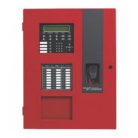
Diagram showing the flap, instructions, and controls/indicators on the system 800 panel.
Lists controls and indicators with their corresponding numbers, access levels, and page references for description.
Detailed table of controls, their access levels, and specific functions like starting alarms or resetting the panel.
Details on Edit, Esc, Previous/Next, and numeric buttons, including their functions and access levels.
Explanation of the steady and off states for Fire and Fire Routing Activated (red) indicators.
| Brand | Honeywell |
|---|---|
| Model | System 800 |
| Category | Fire Alarms |
| Language | English |
