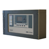
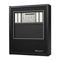
Do you have a question about the Honeywell NOTIFIER IFS-2600 and is the answer not in the manual?
Covers safety warnings, wire sizing, static sensitivity, and general installation advice.
Advises on radio frequency energy effects and potential interference with communications.
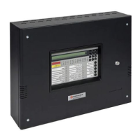
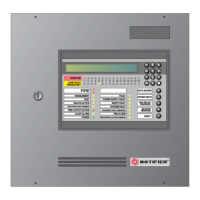
Details the IFS-2600 Fire Indicator Panel's features, display, keypad, and programmability.
Lists important safety advisories regarding approvals, programming, and radio frequency energy.
Details cabinet material, finish, and physical dimensions for various configurations.
Lists AC operational voltage, internal power supplies, fuses, and EOL resistor values.
Lists relevant Australian standards and approval numbers for the equipment.
Specifies the operating temperature and humidity ranges for the panel.
Lists the hardware required for expanding the system's zone capacity.
Lists the hardware required for additional relay outputs.
Details the 24 VDC, 3.0A main power supply's AC input and output specifications.
Details the 27.3V DC, 1.5A battery charger's AC input and output specifications.
Provides critical information on battery reconnection after power failure and testing.
Details the 5VDC, 2A internal power supply for panel operations.
Details the use and requirements of an external 27VDC supply for large systems.
Lists compatible battery types and manufacturers for the panel.
Describes the main control, termination, and power supply boards and their functions.
Explains the panel's protection against voltage transients using various components.
Details quiescent and alarm current draw for different zone configurations.
Explanation of Alarm Zone Facilities (AZF) and their role in alarm detection.
Details current levels for fault, quiescent, and alarm states in AZF circuits.
Lists fuses for protection and current limiting for AZF circuits.
Describes the automatic reset mechanism for overloaded zones.
Description of the serial printer port, its settings, and usage for reporting.
Explains how to program the panel using DOS-based software via the printer port.
Details voltage calibration steps for the main power supply and battery charger.
Details calibration for the power supply comparator reference voltage.
Lists fixed test point voltages for 5VDC and 12VDC supplies.
Provides voltage settings for adjusting the alarm threshold comparator.
Provides voltage settings for adjusting the fault threshold comparator.
Explains how to reset the panel to factory defaults using the JP3 jumper.
Describes how to inhibit program changes using the JP4 jumper.
Explains how to restart the CPU using the JP5 jumper.
Details disabling the door holder output using the JP2 jumper.
Explains enabling external PSU monitoring using the JP1 jumper.
Describes setting zone expansion board addresses using JP1-JP7 jumpers.
Checklist for verifying installed equipment like boards, transformers, and wiring.
Pre-power-up inspection checklist for general condition and security.
Steps to follow after connecting power and batteries for initial startup.
Procedures for testing LEDs, LCD, zone detection, and various outputs.
A template for documenting faults, their corrections, and the date of testing.
Details the function, color, and buzzer status for each panel LED indicator.
Provides a step-by-step guide for fire officers responding to alarms.
Divides panel functions into Fire Fighter, Global, and Zone categories.
Explains key firefighter functions: Acknowledge, Reset, and Isolate.
Describes how to isolate bells and warning systems from alarm activation.
Explains how to perform a battery performance test as per AS4428.
Details the automated panel test procedure for comprehensive system checks.
Describes the procedure for on-site testing of detector zones.
Explains how to isolate and reset Ancillary Output (ACF) functions.
Details the procedure for testing a zone's alarm detection capability.
Explains how to perform fault tests on specific or all zones.
Describes how to isolate specific zones or all zones from the system.
Explains how to reset specific zones or all zones to normal state.
Covers Ancillary Trip, Alarm Verification, and Time settings.
Details zone types, input delays, and output configurations.
Lists programmable relay functions and mapping logic.
Shows the default configuration for ACF, AVF, Time, Zones, and Relays.
Explains how to use keypad buttons for programming mode.
Outlines the menu structure: Zones, Global, Relay, Print.
Lists available zone types and their output options.
Details how to map relays to zones and select relay types.
Covers ACF, AVF, Relay, and Time global settings.
Explains how to print the current configuration from RAM.
Describes navigating between Zones, Relays, Global, and Print menus.
Explains how to save changes and exit programming mode.
Guides through selecting zones and configuring their types.
Details how to configure zone output functions like Indicate, Bell, General Alarm.
Explains how to select and configure relays by type and mapping.
Lists available relay types such as Isolate, Brigade, Fault, and Map types.
Explains how to map relays to specific zones for activation.
Describes accessing and configuring global programming settings.
Sets the behavior of the Ancillary Output (ACF) as latching or non-latching.
Sets the timeout period for the Alarm Verification Facility (AVF).
Configures relay mapping starting from a specified relay and zone.
Explains how to print the current panel configuration from RAM.
Guides on how to set the panel's current date and time.
Explains different zone types and their corresponding input delays.
Details the behavior of latching zone types upon alarm.
Details the behavior of non-latching zone types upon alarm.
Explains the operation of time delay zone types for smoke detection.
Lists and describes different output types for zone alarms.
Explains the purpose and function of the Alarm Verification Facility.
Details programmable options for AVF timeout periods.
Explains the use of Ancillary Trip for shutting down systems during a fire.
Details programmable options for ACF behavior (latching/non-latching).
Lists standard outputs that can be mimicked by relays.
Explains the AND mapping logic for relay activation based on multiple zones.
Explains the OR mapping logic for relay activation based on any zone.
Explains the FAULT mapping logic for relay activation based on zone faults.
Explains FAULT/ISOLATE mapping logic for relay activation.
Explains ISOLATE mapping logic for relay activation.
Provides definitions for abbreviations and technical terms used throughout the manual.
Summarizes MCP loops, detection zones, and relay output wiring.
Details cautions for Bell, ACF, Warning System, and Door Holder outputs.
Cautions for auxiliary power, MIMIC data, AC input, and battery connections.
Covers battery connection polarity and door holder AC transformer input.
Details the default behavior of output relays like Standby, Brigade, and Fault.
Provides fields for configuring global system parameters like date.
Details configurable options for ACF and AVF settings.
Table for programming zone types and input delays for zones 1-32.
Continuation of table for zone type settings, covering zones 33-64.
Table for programming zone output functions for zones 1-32.
Continuation of table for zone output settings, covering zones 33-64.
Table for mapping relays to various functions for relays 1-32.
Continuation of table for relay mapping, covering relays 33-64.
Visual representations of the main keypad, displays, and firefighter controls.
Diagrams for overall system connections and detector wiring.
Diagrams for ancillary devices, ASE units, and fan control systems.
Diagrams for connecting EVAC systems, including master and slave units.
| Model | IFS-2600 |
|---|---|
| SLC Loops | 1 |
| Power Supply (Current) | 3.0 A / 1.5 A |
| Humidity Range | 10% to 93% |
| Compatibility | Notifier |
