Do you have a question about the Honeywell 6808 and is the answer not in the manual?
Describes the fundamental aspects of the 6808 system.
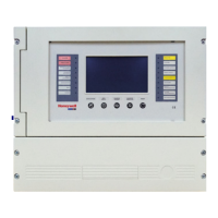
Details the physical components and capabilities of the 6808 panel.
Explains how the 6808 links with other panels for communication.
Lists advanced software functionalities like drift compensation and JumpStart.
Provides information about the manual's purpose and terminology.
Defines key terms and abbreviations used throughout the manual.
Lists hardware products compatible with the 6808 system.
Details FCC compliance and connection requirements for telephone lines.
Outlines UL requirements for system installations.
General UL requirements applicable to all installation types.
Specific UL requirements for central station systems.
Specific UL requirements for local protected systems.
Specific UL requirements for remote station systems.
Requirements for CO detection systems as per NFPA 720.
Details minimum configurations to meet NFPA requirements.
Lists items included in the 6808 shipment for verification.
Specifies environmental conditions for proper panel installation and operation.
Advises on downloading the latest software for optimal system performance.
Provides terminal block descriptions and electrical ratings.
Guidelines to prevent induced noise and ensure proper wiring practices.
Illustrates the layout of the 6808 circuit boards and annunciator.
Guides on determining system current draw and battery needs.
Steps to follow when using the current draw worksheet.
Table for calculating current draw for SK SLC devices.
Table for calculating current draw for SD SLC devices.
Provides standby load calculations for 24 and 90 hours.
Instructions for physically installing the control panel cabinet.
Precautions to avoid water damage to the system through conduits.
Procedure for removing the control panel assembly from its cabinet.
Information on connecting the panel via Ethernet for IP communication.
Details on connecting the AC power source to the control panel.
Guidelines for connecting and using batteries for system power.
Information on using the RBB accessory cabinet for larger batteries.
Information on wiring SBUS modules and calculating distances.
Guides on determining wire gauge and maximum distance for SBUS modules.
Illustrates Class B SBUS wiring configurations.
Steps for installing the 5860 remote LCD annunciator.
Instructions for flush or surface mounting the 5860 annunciator.
Details on flush mounting the 5860 annunciator with or without an electrical box.
Instructions for surface mounting the 5860 annunciator.
Shows how to connect the 5860 annunciator to the main panel.
Steps for installing the 6855 remote annunciator.
Instructions for flush or surface mounting the 6855 annunciator.
Details on flush mounting the 6855 annunciator.
Instructions for surface mounting the 6855 annunciator.
Steps for installing the 6860 remote annunciator.
Instructions for flush or surface mounting the 6860 annunciator.
Details on flush mounting the 6860 annunciator.
Instructions for surface mounting the 6860 annunciator.
Shows how to connect the 6860 annunciator to the main panel.
Steps for installing the 5824 interface module for printers.
Configuring options for the 5824 printer interface module.
Overview of the 5880 LED I/O module and its installation.
Illustrates the layout of the 5880 board with terminals and DIP switches.
Details how to connect the 5880 module to the main control panel.
Instructions for wiring LEDs to the 5880 module.
Explains how to wire dry contact inputs to the 5880 module.
Covers installation of the 5865-3 and 5865-4 LED annunciators.
Shows how to connect the 5865 annunciator to the panel via SBUS.
Instructions for mounting the 5865 annunciator to electrical boxes.
Explains how to configure SBUS modules, including assigning IDs.
Details the process of assigning unique IDs to SBUS modules using DIP switches.
Discusses SBUS bandwidth usage and tools for calculation.
Instructions for connecting telephone lines to the panel.
Information on using built-in outputs for notification or auxiliary power.
How to install conventional notification appliances.
Wiring diagram for Class B notification appliance circuits.
Wiring diagram for Class A notification appliance circuits.
Details on installing auxiliary power circuits for various applications.
Information on using the panel's built-in programmable relays.
Describes the dedicated Form C trouble relay.
How to install and configure the two Form C programmable relays.
Information on connecting to remote stations.
Steps for installing the Keltron Model 3158 for receiver connection.
Connects the panel to a municipal fire alarm box using the 5220 module.
Using the 5220 module for NFPA 72 polarity reversal reporting.
Details using the 7644-L8 module for polarity reversal.
Instructions for using the SD500-ARM for polarity reversal.
Using the MR-201/T relay for polarity reversal.
Connecting a remote station transmitter using dry contacts.
Describes the capabilities of the 6808 for linking panels.
Details how 6808 panels can be linked for common communication.
Outlines methods for connecting panels using fiber optics or copper wire.
Explains the use of SK-NIC for linking panels.
Details wiring the SK-NIC network interface card to panels.
Information on SK-FML and SK-FSL fiber optic modules.
Details on the SK-NIC mounting kit for cabinet or external installation.
Steps for properly mounting the SK-NIC inside the 6808 cabinet.
Illustrates twisted pair wiring for panel communication.
Illustrates multi-mode fiber optic wiring for panel communication.
Diagram showing single-mode fiber optic wiring between panels.
Diagram showing combined fiber optic and twisted pair wiring.
Instructions for setting the panel ID using DIP switches.
Tools for diagnosing network performance and connectivity.
Utility to test network connectivity and response time of panels.
Displays statistics indicating network performance.
How to program network options using the built-in annunciator or HFSS software.
Shows connected panels and allows adding guest panels to the network.
Allows editing panel and site names within the network.
Process for changing the network panel ID for unique identification.
Steps for establishing communication between the panel and a computer.
Explains how access codes control user access to panel functions.
Configuration for reporting events to a central station.
Specifies event reporting details for each panel in the link.
Distributes network option changes to other panels in the system.
A quick reference guide for network management features.
Lists SK SLC devices compatible with the control panel.
Lists SD SLC devices compatible with the control panel.
Information on SWIFT wireless devices and their gateway.
Details the maximum number of devices supported per system.
General wiring requirements for all SLC devices.
Specific wiring requirements for SK SLC modules.
Illustrates how to wire SLC loops for Class A installations.
How to assign addresses to SK devices using rotary dials.
Instructions for wiring SK heat and smoke detectors.
Instructions for wiring SD detectors.
How to address SD detectors and modules.
Setting addresses for SLC devices using DIP switches.
Information on the SK-WGI wireless gateway.
Details power connections for the wireless gateway.
Overview of the JumpStart feature for automated system setup.
How JumpStart determines and assigns input points and zones.
How JumpStart assigns output circuits to groups.
Step-by-step guide to running the JumpStart auto-programming feature.
Explains the concept of mapping events to outputs.
Details how input points are assigned to input zones.
Shows how to assign notification and relay output circuits to groups.
Explains how to map panel, zone, and site events to output patterns.
Example showing LED points mapped to zones and output groups.
How to program the panel using the HFSS software suite.
How to program the panel using the on-board or remote annunciator.
Procedure for accessing and leaving the programming menu.
Navigation guide for moving through programming menus.
How to make selections and enter data within programming screens.
A reference table of all program menu options and their defaults.
UL 864 programming requirements and limitations.
Lists available modules for programming within the panel.
Features available for editing modules, including name and wiring class.
Instructions for modifying a module's ID number.
How to assign user-friendly names to hardware modules.
How to modify specific options for each module.
Steps to add a new hardware module to the system.
Procedure for removing a module from the system.
How to view a list of all modules installed in the system.
Options for editing and viewing zone points and properties.
Features for editing zone name, properties, and accessory options.
How to assign a descriptive name to a zone.
Editing zone properties like alarm delay and heat sensitivity.
Explains different zone alarm delay types and their descriptions.
Setting the response temperature for heat detectors in a zone.
Configuring zone accessory options like cadence patterns and local zone settings.
How to view the points assigned to a specific zone.
Options for programming output groups and their characteristics.
Editing group names and properties like template override and cadence.
How to view the points assigned to a specific group.
Modifying output group templates and selecting included groups.
Changing characteristics of individual input and output points.
Programming individual points on the SLC loop.
Details on selecting device types and their functions for points.
Programming points for internal or external power modules.
Programming points for 5880 and 5865 modules.
Customizing software options affecting general system operation.
Settings for communication parameters like auto test and phone lines.
Configuring the automatic test report time and interval.
Settings for phone line configuration, dialing, and monitoring.
Configuring Ethernet settings for network communication.
Settings for Ethernet, Cellular, and Old Alarm timers.
Adjusting dialing and reporting gain levels.
Setting water flow delay, alarm verification, AC report delay, and clock format.
Programming a delay for water flow switch alarms.
Setting the alarm verification time to prevent false alarms.
Adjusting the delay before sending a low AC report.
Selecting the AC line frequency for accurate time calculation.
Setting the system clock display format.
Configuring automatic event resound time after silencing.
Turning on/off features like strobe sync, auto display, and single key ack.
Setting the start and end dates for Daylight Saving Time.
Creating a custom message to display on the panel LCD.
Configuring the panel to accept SD or SK SLC device protocols.
Running JumpStart again for incremental updates after initial setup.
Resetting the panel to factory default settings, losing all programming.
Lists the factory default access codes for users and installers.
Describes the control panel's annunciator interface.
Explains the information displayed on the control panel's LCD.
How to customize the banner message displayed on the panel.
Overview of navigating the control panel's menu system.
A chart detailing the main menu options and their descriptions.
Guide on navigating through the panel's menus using arrow keys.
Core operational procedures for the control panel.
How to set the system's current time and date.
Procedure for disabling or enabling specific points within the system.
Prevents an output group from being activated by system mapping.
How to access and view the system's event history log.
Acknowledging the oldest un-acknowledged event with a single key press.
Initiating and conducting a fire drill test on the system.
Testing annunciator LEDs, PZT, and LCD display for proper function.
Performing a walk test of the fire alarm system.
Testing the system's communicator functionality.
Registering the system with AlarmNet manually.
How to silence alarms or troubles using keys or switches.
Resetting alarms using keys or switches.
Checking detector sensitivity compliance with NFPA 72.
Viewing the status of a specific point, including troubles and sensitivity info.
How to view the location of active alarms or troubles.
Accessing panel model, serial number, and firmware version.
Updating panel firmware and propagating it to other network panels.
Displaying Ethernet configuration details.
Viewing AlarmNet status and cell strength.
Information on the temporary PIN for FACP replacement.
Describes panel behavior in different modes like Normal, Alarm, Trouble.
Details panel behavior across various operation modes.
Describes multi-site annunciator features and user access.
Information on Double Interlock and Single Interlock Zone releasing.
Lists approved releasing solenoids and their electrical ratings.
Operation and conditions for single interlock zone releasing.
Conditions needed for pre-alert output activation in single interlock zones.
Conditions for general alarm and release output activation.
Operation and conditions for double interlock zone releasing.
Illustrates the operation cycle of smoke alarm verification.
Features and macro key functionality of the 6860 annunciator.
Procedure to access the F-Key recording menu.
Steps for recording an F-Key macro for custom functions.
How to cancel an ongoing F-Key macro recording session.
Procedure for deleting a recorded F-Key macro.
How to activate a previously recorded F-Key macro.
Using F-Key events to activate outputs without status display changes.
Disabling output group mapping for testing purposes.
Lists compatible receivers and their formats.
Table listing compatible receivers and their formats.
Details SIA reporting formats and event codes.
Details Contact ID reporting formats and event codes.
Comprehensive table of reporting formats and event codes.
Explains SIA event format and PI modifier usage.
Examples of SIA panel PI modifier reporting.
Details the SIA panel communicator event format (EEPPMMZZZZ).
Examples of SIA panel PI modifier reporting.
Examples of SIA reporting formats for various events.
Offers suggestions for resolving hardware problems.
Lists common problems and their suggested solutions.
Recommendations for system inspection and testing schedules.
How event history can be useful for tracking issues.
Overview of built-in tools for testing points and SLC devices.
Tool to locate a specific device on an SLC loop.
Tool to locate multiple SLC devices on a single search.
Feature to toggle I/O points for testing output mapping.
Table showing minimum impedances causing earth ground faults.
Table to track SLC device points, zones, and groups.
Lists notification appliances compatible with the control panel.
Table listing compatible notification appliances.
Lists compatible two-wire smoke detectors and loop capacity.
Lists UL-listed four-wire smoke detectors and their current draw.
Table of compatible four-wire smoke detectors.
Lists compatible UL-listed door holders.
Lists compatible UL-listed relays for the control panel.
Table of compatible relays.
Lists compatible 520Hz signaling speakers.
Lists compatible 520Hz low frequency bases.
Lists available characters and their numeric designators for programming.
Provides an example of editing names using the built-in programmer.
Table showing available receiver numbers per panel.
Lists available cadence patterns for the control panel.
Checklist for cyber security tasks during panel installation.
Classification of security levels for communication, data, physical, and access control.
Table summarizing basic operations and their corresponding tasks.
| Brand | Honeywell |
|---|---|
| Model | 6808 |
| Category | Fire Alarms |
| Language | English |