6808 Manual –LS10146-001SK-E:C 10/09/2017 5
Contents
Section 1: Introduction ................................................................................................................................................... 10
1.1: Overview of Basic System...............................................................................................................................................................................10
1.1.1: Hardware Features................................................................................................................................................................................10
1.1.2: Common Communication / Annunciation Link System Hardware Features.......................................................................................10
1.1.3: Software Features .................................................................................................................................................................................10
1.2: About this Manual............................................................................................................................................................................................10
1.2.1: Terms Used in this Manual...................................................................................................................................................................10
1.3: Compatible Products........................................................................................................................................................................................11
Section 2: Agency Listings, Approvals, and Requirements........................................................................................ 14
2.1: Federal Communications Commission (FCC).................................................................................................................................................14
2.2: Underwriters Laboratories (UL)......................................................................................................................................................................14
2.2.1: Requirements for All Installations........................................................................................................................................................14
2.2.2: Requirements for Central Station Fire Alarm Systems ........................................................................................................................15
2.2.3: Requirements for Local Protected Fire Alarm Systems .......................................................................................................................15
2.2.4: Requirements for Remote Station Protected Fire Alarm Systems........................................................................................................15
2.2.5: Requirements for the Installation of Carbon Monoxide (CO) Detection and Warning Equipment, NFPA 720..................................15
2.2.6: NFPA Requirements.............................................................................................................................................................................15
Section 3: Before You Begin Installing ......................................................................................................................... 16
3.1: Inventory..........................................................................................................................................................................................................16
3.2: Environmental Specifications..........................................................................................................................................................................16
3.3: Software Downloads........................................................................................................................................................................................16
3.4: Electrical Specifications ..................................................................................................................................................................................16
3.5: Wiring Specifications.......................................................................................................................................................................................17
3.6: Board Assembly Diagram................................................................................................................................................................................19
3.7: Calculating Current Draw and Standby Battery ..............................................................................................................................................19
3.7.1: Current Draw Worksheet Requirements...............................................................................................................................................19
Current Draw Worksheet for SK SLC Devices......................................................................................................................................20
Current Draw Worksheet for SD SLC Devices......................................................................................................................................23
3.7.2: Maximum Battery Standby Load..........................................................................................................................................................25
Section 4: Control Panel Installation............................................................................................................................. 26
4.1: Mounting the Control Panel Cabinet...............................................................................................................................................................26
4.1.1: Preventing Water Damage....................................................................................................................................................................26
4.1.2: Removing the 6808 Assembly from the Housing.................................................................................................................................26
4.1.3: Ethernet Connection .............................................................................................................................................................................26
4.2: AC Connection.................................................................................................................................................................................................27
4.3: Battery Power ..................................................................................................................................................................................................27
4.3.1: Battery Accessory Cabinet ...................................................................................................................................................................28
Installing the RBB Accessory Cabinet and Batteries .............................................................................................................................28
4.4: SBUS Wiring ...................................................................................................................................................................................................30
4.4.1: Calculating Wiring distance for SBUS modules ..................................................................................................................................30
4.4.2: Wiring Configurations..........................................................................................................................................................................31
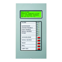
4.5: 5860 Remote LCD Annunciator Installation ...................................................................................................................................................32
4.5.1: Mounting the 5860................................................................................................................................................................................32
Flush Mounting.......................................................................................................................................................................................33
Surface Mounting ...................................................................................................................................................................................34
4.5.2: Model 5860 Connection to the Panel......................................................................................
..............................................................34
4.6: 6855 Remote Annunciator Installation ............................................................................................................................................................35
4.6.1: Mounting the 6855................................................................................................................................................................................35
Flush Mounting.......................................................................................................................................................................................35
Surface Mounting ...................................................................................................................................................................................37
4.7: 6860 Remote Annunciator Installation ............................................................................................................................................................38
4.7.1: Mounting the 6860................................................................................................................................................................................38
Flush Mounting.......................................................................................................................................................................................39
Surface Mounting ...................................................................................................................................................................................40
4.7.2: 6860 Connection to the Panel............................................................................................
...................................................................41
4.8: 5824 Serial/Parallel Interface Module Installation..........................................................................................................................................41
4.8.1: Selecting 5824 Options.........................................................................................................................................................................42

 Loading...
