16 6808 Manual — P/N LS10146-001SK-E:C 09/28/2017
Section 3: Before You Begin Installing
This section of the manual is intended to help you plan your tasks to facilitate a smooth installation. Please read this section thoroughly,
especially if you are installing a 6808 panel for the first time.
3.1 Inventory
When the 6808 shipment is received, check that all the parts have been included in the shipment. The shipment consist of one of each of
the following:
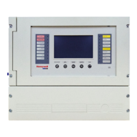
• main circuit board with display
• backbox with door
• plastic bag containing two keys, screws, cables, and ten 4.7K ohm end-of-line resistors
• manual
3.2 Environmental Specifications
It is important to protect the 6808 control panel from water. To prevent water damage, the following conditions should be FOLLOWED
when installing the units:
• Mount indoors in dry locations only
• Do not mount directly on exterior walls, especially masonry walls (condensation)
• Do not mount directly on exterior walls below grade (condensation)
• Protect from plumbing leaks
• Protect from splash caused by sprinkler system inspection ports
• Do not mount in areas with humidity-generating equipment (such as dryers, production machinery)
When selecting a location to mount the 6808 control panel, the unit should be mounted where it will NOT be exposed to temperatures
outside the range of 0°C-49°C (32°F-120°F) or humidity not exceeding 93% noncondensing.
3.3 Software Downloads
In order to supply the latest features and functionality in fire alarm and life safety technology to our customers, we make frequent
upgrades to the embedded software in our products. To ensure that you are installing and programming the latest features, we strongly
recommend that you download the most current version of software for each product prior to commissioning any system. Contact Tech-
nical Support with any questions about software and the appropriate version for a specific application. HFSS Honeywell Fire Software
Suite is available at www.silentknight.com.
3.4 Electrical Specifications
Table 3.1 list the terminal block on the 6808 as well as a description of the each individual terminal and their respective electrical rating.
Terminal No.
Label
Description
Rating
Group Individual Voltage Current
Terminal Block 1 TELCO 1 RING Phone Line 1 Telco Ring
TIP Phone Line 1 Telco Tip
PHONE 1 RING Phone Line 1 Phone Ring
TIP Phone Line 1 Phone Tip
TELCO 2 RING Phone Line 2 Telco Ring
TIP Phone Line 2 Telco Tip
PHONE 2 RING Phone Line 2 Phone Ring
TIP Phone Line 2 Phone Tip
Terminal Block 2 SLC IN – Used for Class A installations 32 VDC 150 mA
+
SLC OUT – SLC terminals 32 VDC 150 mA
+
SLC PROG – Used for programming SLC
Detectors
32 VDC 150 mA
+
Terminal Block 3 SBUS Out B SBUS Communication 5 VDC 100 mA
A
+ SBUS Power 24 VDC 1.0 A
–
Terminal Block 4 BATTERY + To Positive battery terminal 24 VDC Up to 35 Ah (see Section
4.3 for details)
– To Negative battery terminal
Table 3.1 Terminal Descriptions and Electrical Specifications

 Loading...