Do you have a question about the Honeywell Notifier LCD2-80 and is the answer not in the manual?
General limitations of fire alarm systems and their inability to guarantee protection against property damage or loss.
Explains how smoke detectors may fail to sense fires or provide adequate warning due to various factors.
Details limitations of heat detectors, focusing on their role in property protection rather than life safety.
Covers issues with audible/visual devices, power dependency, compatibility, and maintenance requirements.
Warnings regarding power disconnection, component handling, and the importance of reading manuals before installation.
Requirements for re-testing the system after any programming or hardware changes to ensure proper operation.
Specifications for operating environment, wiring, static-sensitive components, and lightning protection.
FCC and Canadian regulatory notices concerning radio frequency emissions from the equipment.
Discusses UL 864 certification status and features/products requiring Authority Having Jurisdiction approval.
Lists the LCD2-80's main features, display capabilities, operational modes, and connections.
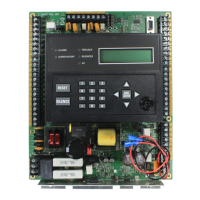
Identifies physical components, connectors, DIP switches, and indicators on the LCD2-80 board.
Details the voltage and current consumption specifications for the LCD2-80 device.
Explains terminal connections (TB1, TB2), NUP, and keyswitch interfaces for the LCD2-80.
Describes LED indicators, address switches, ACS/TERM mode switch, and DIP switch functions.
Instructions for setting DIP switches and the ACS/TERM mode switch to configure the device for Terminal Mode.
Details requirements and diagrams for connecting the LCD2-80 in Terminal Mode via EIA-485.
Instructions for setting DIP switches and the ACS/TERM mode switch to configure the device for ACS Mode.
Details requirements and diagrams for connecting the LCD2-80 in ACS Mode via EIA-485.
Explains how to program the LCD2-80 using VeriFire®Tools, covering general and point label settings.
Describes how event and custom messages are displayed in Terminal and ACS modes.
Explains the system's response and message displayed when communication is lost.
Details the specific functions of each button on the LCD2-80 unit.
Provides instructions for proper EIA-485 cable shield termination in various installation scenarios.
Outlines the manufacturer's warranty coverage, conditions, and limitations of liability.
| Display | 80-character backlit LCD |
|---|---|
| Backlight | Yes |
| Compatibility | ONYX Series |
| Mounting | Surface mount |
| Color | Black |
