LCD2-80 Instruction Manual — P/N 53242:B5 07/26/2019 7
Board Layout Product Overview
• System trouble display option.
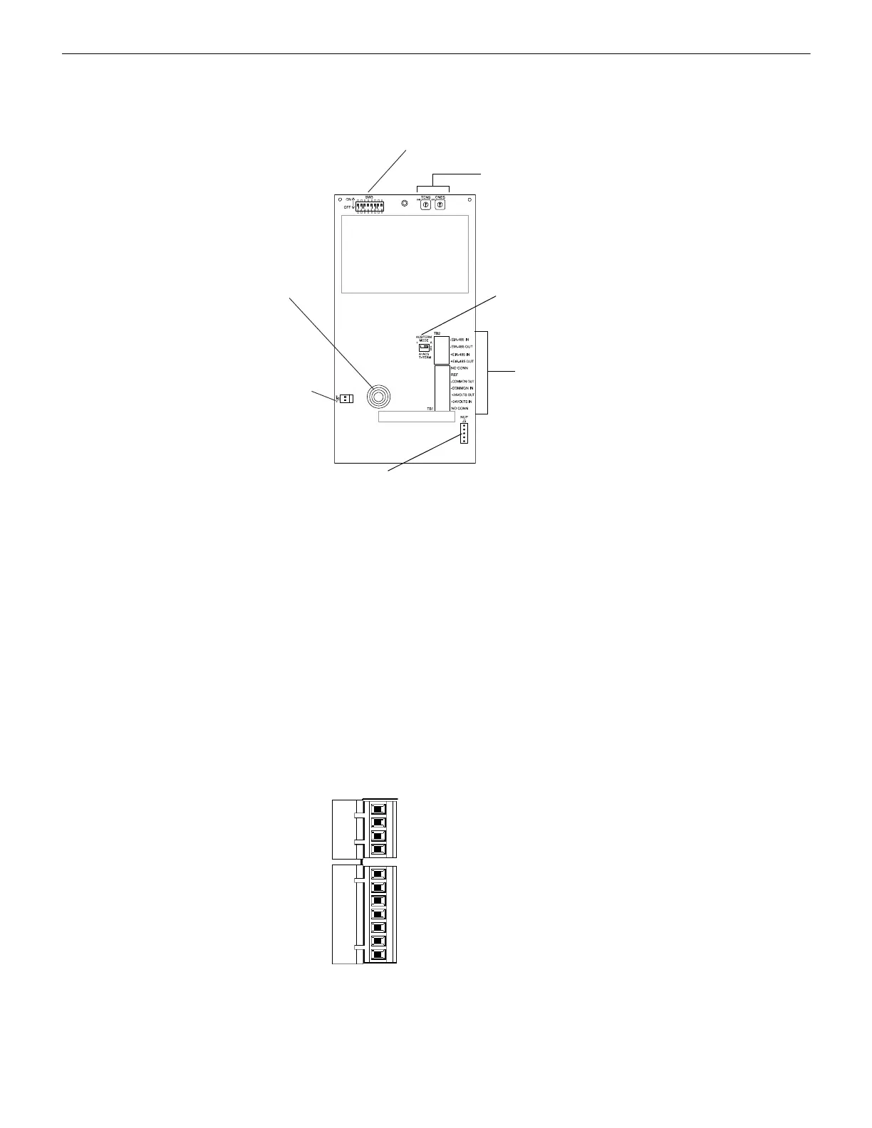
1.3 Board Layout
1.4 Power Specifications
Current Consumption @ 24 VDC
• Normal (no activity): 84 mA
• Lamp Test: 105 mA
• AC Fail (Piezo ON): 45 mA
• AC Fail (Piezo OFF): 28 mA
• Alarm (Piezo ON): 98 mA
• Alarm (Piezo OFF): 85 mA
Include these currents in your power supply loading and battery calculations.
1.5 Connections
1.5.1 Terminal Connections - TB1 and TB2
These connections provide 24 VDC operating power (TB1) and EIA-485 connections (TB2) to the LCD2-80.
The connections must be power-limited.
Power connections are illustrated below. Refer to “Terminal Mode EIA-485 Connections” on page 11 and “ACS Mode EIA-485 Con-
nections” on page 14 for TB2 connection illustrations.
Address Switches (SW1, SW2)
See Section 1.6.3 on page 9
DIP Switches (SW3)
See Section 1.6.5 on page 9
AKS-1B (J2)
See Section 1.5.3
on page 8
Terminal Connections
(TB1, TB2)
See Section 1.5.1 on
page 7.
Piezo Sounder (SP1)
See Section 1.6.2 on
page 9
LCD280wmodeswtch.wmf
NUP Connection (J3)
See Section 1.5.2 on page 8
ACS/TERM Mode Switch
(SW10)
See Section 1.6.4 on
page 9.
Figure 1.1 LCD2-80 Board Layout
-EIA-485 In
-EIA-485 Out
+EIA-485 In
+EIA-485 Out
No connection
Reference
-Common Out
-Common In
+24 Volts Out
+24 Volts In
No connection
TB1
TB2
Figure 1.2 TB1, TB2 Connections

 Loading...


