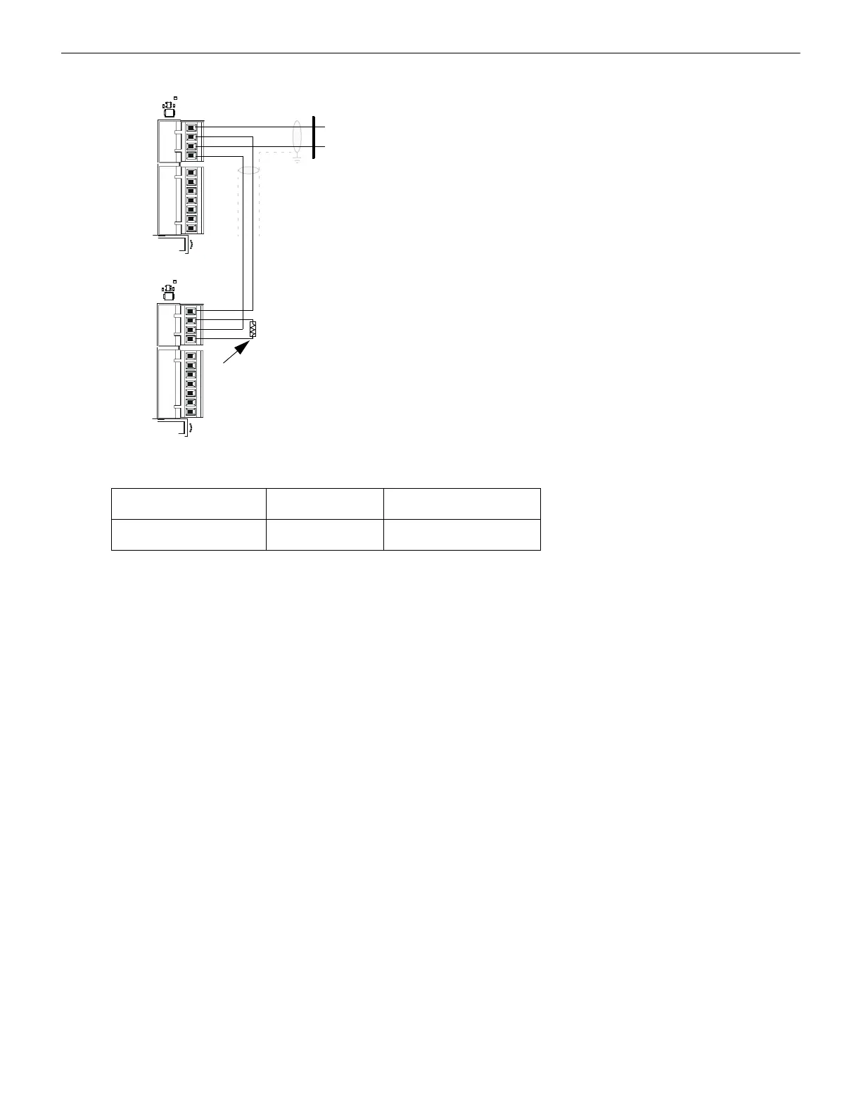
Figure 3.2 ACS Mode EIA-485 Connections
TB2
TB1
TB2
TB1
4
3
2
1
4
3
2
1
7
6
5
4
3
2
1
4
3
2
1
7
6
5
Terminatin
g Resistor
Observe the following requirements when connecting the EIA-485 circuit:
• The LCD2-80 requires operating power. Connect 24 VDC power to TB1 terminal 3(+)
and TB1 terminal 4 (-). Power connections are supervised and power-limited.
• The EIA-485 loop can support up to 32 devices on the loop subject to power supply
loading limitations (ACS, LDM, and LCD-type devices)
• 6000 feet maximum loop length from the CPU to the last device.
• Do not “T-Tap” the EIA-485 circuit—it will not function properly. Wire as illustrated.
• Use twisted, shielded pair cable with a characteristic impedance of approximately 120
ohms.
• EIA-485: 5.5 VDC max; 60 mA max.
• A UL listed 120-ohm terminating resistor (R-120) must be installed on the last device
on the EIA-485 circuit.
• Refer to Appendix A for shield termination instructions.
• Terminal block connections on the Fire Alarm Control Panel are listed in Table 3.1; for
illustrations, refer to your FACP manual.
• A separate reference wire is required for NFS2-3030 applications using ACS
annunciators which are not in the same backbox as the fire alarm control panel’s
CPU.
(-)
EIA-485 terminals on CPU
(+)
Cabinet

 Loading...


