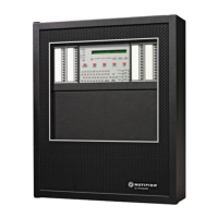
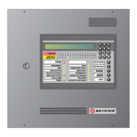
Do you have a question about the Honeywell Notifier AM12-24 and is the answer not in the manual?
Guidelines to avoid equipment damage and ensure safe operation.
Details key features and capabilities of the AM1224 fire panel.
Specifies requirements for connecting the panel to the mains power supply.
Details the procedure for connecting the 230Vac power supply to the panel.
Describes connection types and wire specifications for detection lines.
Details the functionality and specifications of general alarm and fault relays.
Provides a layout of the main circuit board with key components and jumpers.
Describes the functionality and terminals of the line expansion card.
Describes the functionality and terminals of the 16-output optional card.
Shows the layout of the display board with jumpers and LEDs.
Explains the function of each button and LED on the front panel.
Describes the meaning of each LED indicator on the front panel.
Details how to use the keyboard for data entry and navigation.
Explains how zone alarm conditions are displayed on the panel.
Explains how zone fault conditions are displayed on the panel.
Explains how system trouble conditions are displayed on the panel.
Explains how zone test conditions are displayed on the panel.
Configures individual detector lines, including naming and zone assignment.
Configures output activation, naming, and CBE equations.
Defines zones by grouping lines and associating them with areas.
| Brand | Honeywell |
|---|---|
| Model | Notifier AM12-24 |
| Category | Fire Alarms |
| Language | English |
