PAGINA - 4 Installation and programming manual AM-1224
NOTIFIER ITALIA Doc. M-124.1-AM1224-ENG Rev A.1 AM-1224_manu
I
I
N
N
S
S
T
T
A
A
L
L
L
L
A
A
T
T
I
I
O
O
N
N
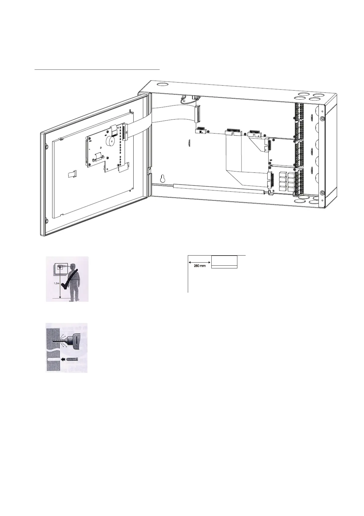
DIMENSIONS FOR WALL MOUNTING
The control panel is designed for wall mounting through 4 blocking dowels (on brick walls) or thread studs (on
panels etc.) The maximum screw diameter is 5 mm.
The control panel should not be installed near heat sources (radiators, heaters, etc.).
The panel may be opened unscrewing the top cover.
Wires of detector lines, auxiliary devices and power supply may be passed into the panel using knock-out holes
running them along the cabinet internal side providing sufficient length especially for those connected to the
CNAL terminal block.
230 Vac wire power supply must be fixed inside of the control panel. For the 230 Vac wire power supply must
be interrupted by an external shut down switch.
For installation in a corner it is
necessary to have a distance of
280mm to let the frontal panel
open.
With 5 automatic blocks (brickwoork
wall) or selfscrew (prefabbricated
panel) it is possible tha wall mounting.
Diameter max of the selfcrew: 5mm
The contol panel has to be wall
mounted in order to allow a clear
visibility of the disply and an easy
access for the user.
For example 1.5 m height allow an
optimal display vision.

 Loading...


