AM-1224 Installation and programming manual PAGINA - 5
AM-1224_manu Doc. M-124.1-AM1224-ENG Rev A.1 NOTIFIER ITALIA
M
M
a
a
i
i
n
n
s
s
2
2
3
3
0
0
V
V
a
a
c
c
c
c
o
o
n
n
n
n
e
e
c
c
t
t
i
i
o
o
n
n
s
s
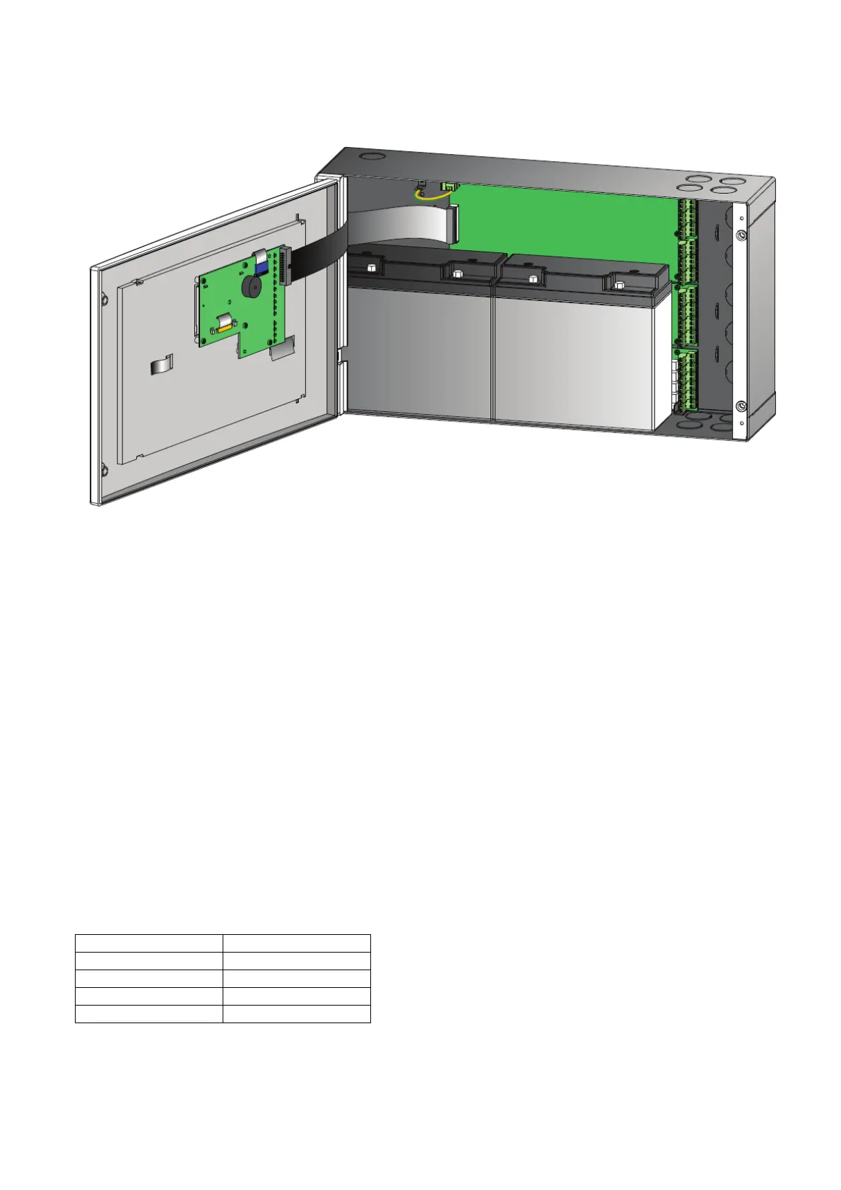
The power supply cable must preferably pass near the relative terminal block.
The connection to the 230 V power supply shall be made through 3 conductors cable (phase, neutral, earth).
The registration of the earth conductor coming from the main shall be connected to the CNAL terminal block and
must be fixed to the cabinet so that it can not accidentally be teared from the terminal.
Power supply connection shall be made in the following sequence:
1 - Open the 230 Vac power supply general switch.
2 - Disconnect terminal block CNAL from the control panel.
3 - Connect the power supply cable.
4 - Reconnect terminal block CNAL.
5 - Close the mains general switch.
6 - Install and connect batteries as specified in this manual.
7 - Close the control panel.
D
D
e
e
t
t
e
e
c
c
t
t
i
i
o
o
n
n
L
L
i
i
n
n
e
e
s
s
Detectors' connection line may be two wires (current consuming detectors) or three wires (separately powered
detectors with alarm on N.O. contact).
Wire type: preferably shielded – two conductors.
Table of minimum section of wire relating to distance:
Up to 500 mt. 2 x 0.5 mm²
Up to 1.000 mt. 2 x 1 mm²
Up to 1.500 mt. 2 x 1.5 mm²
Up to 2.000 mt. 2 x 2 mm²
Fino a 3.000 mt. cavo 2 x 3 mm²

 Loading...


