6808 Manual — P/N LS10146-001SK-E:C 09/28/2017 45
Control Panel Installation
Wire dry contacts as shown in Figure 4.33. Notice grouping of terminals; power terminals are shared by two inputs.
Figure 4.33 Dry Contact Wiring
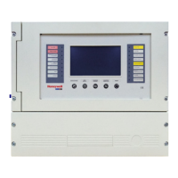
4.10 5865-3 / 5865-4 LED Annunciator Installation
The 5865-3 and 5865-4 are LED annunciators. The 5865-4 has 30 mappable LEDs, remote silence and reset key switches, and a general
system trouble LED. The 5865-3 has 30 mappable LEDs only. These are arranged as 15 pairs of red (typically used for alarm) and yel-
low (typically used for trouble) LEDs.
Installation of the 5865-3 and 5865-4 is identical. The key switches and the trouble LED follow the behavior of other system annuncia-
tors and do not require any installation steps. The following sub-sections describe how to install the 5865-3 and 5865-4 hardware. Refer
to Section 9 for programming information.
Figure 4.34 5865-3 and 5865-4 Assembly (front view)
Supervised/Power Limited
4.7k
EOL
NOTE: This manual uses “5865” when referring to aspects of the 5865-3 and 5865-4 that are common to both models.
SILENCE
TROUBLE
RESET
5865-4 Board Assembly
Plexiglass plate mounted to LED board at factory.
Do not remove.
5865-4 switches
follow main FACP;
no installation
or programming
required.
Numbers indicate
point numbers for
5865. (They do
not appear on board
assembly.)
12
9
10
11 12
21 22
19 20
29 30
34
5
6
7
8
13
14
15
16
17
18
23
24
25 26
27
28

 Loading...