Home
Honeywell
Fire Alarms
NOTIFIER IFS-2600
Honeywell NOTIFIER IFS-2600 User Manual
5
of 1
of 1 rating
80 pages
Give review
Manual
Specs
To Next Page
To Next Page
To Previous Page
To Previous Page
Loading...
Page
46
IFS-2600
Installa
tion
&
Progra
m
ming
Manual
P/N
100
69
ECN08-00
66
A
PPENDIX
H
IFS-2600
PROGRA
M
MED
OPTIONS
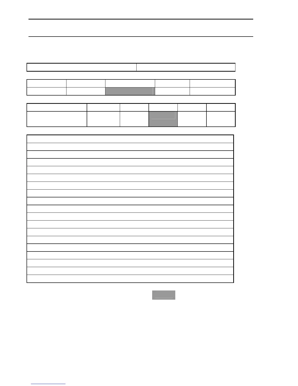
Global
System
Parameters
Date:
/
/
Latch
ND
Non-Latch
ND
Latch
NE
Non-Latch
NE
ACF
Output
Disabled
2
min
3
min
4
min
5
min
Alarm
Verification
(AVF)
Notes:
Programmed
by
Place
an
"X
"
in
the
appropriat
e
box
=
Default
49
51
Table of Contents
Default Chapter
3
Installation Precautions
3
Table of Contents
5
Compatible Detectors
9
Overview
10
Caution
10
Specification
11
Approvals
11
Environmental Limits
11
Power Supply Ratings and Settings
13
INTERNAL 24 VDC (Nom) 3.0A MAIN POWER SUPPLY
13
Internal 27.3V DC 1.5A Battery Charger
13
Internal 5VDC 2A Power Supply
13
External 27Vdc Power Supply
14
Battery Type and Capacities
14
Technical Description
15
General
15
Transient Suppression
15
Current Consumption
15
Azf Description
16
Azf Supervisory Current
16
Overload Protection
16
Zone Overload Self Reset
16
Printer Output
17
Cable Connection
17
Programming by Computer
17
Page 2
18
Pcb2005 Termination Board
18
Internal 5Vdc Power Supply Tp8
18
Power Supply Comparator Reference Voltage Tp10
18
Non Adjustable Test Points
18
Alignment and Adjustment
18
Pcb2006 Power Supply Board
18
INTERNAL 24VDC (Nom) POWER SUPPLY
18
Internal 27.3 VDC Battery Charger
18
EXTERNAL 24VDC (Nom) POWER SUPPLY (if Fitted)
18
Alarm Threshold Comparator Tp7
19
Fault Threshold Comparator Tp6
19
Configuration Jumpers
20
Ifs2004 - Jp3 Default
20
Ifs2004 - Jp4 Program Disable
20
Ifs2004 - Jp5 Cpu Reset
20
Ifs2005 - Jp2 Door Holder Bypass
20
Ifs2006 - Jp1 External Ps Monitoring
20
Ifs804 - Jp1-7 Zone Board Addressing
20
Placing into Operation
21
Equipment as Fitted
21
Initial Checklist
21
Power up Checklist
22
Functional Testing
22
Fault Record
23
Instructions to Operators
24
Indicators
24
Suggested Alarm Procedure
25
Operator Instructions
25
Firefighter Functions
25
Global Functions
26
Zone Functions
28
Fault Test
29
Isolate/Reset
30
Programming
31
Global Options
31
Zone Options
31
Output Relay Options
32
Default Settings
32
Program Mode
33
Programming Mode
33
Programming Hierarchy
33
Zones
33
IFS-2600 Installation & Programming Manual
34
Relays
34
Global
34
Print
34
Main Menu
34
Exit Programming Mode
35
Zone Programming
35
Select Zone
35
Zone Selected
35
Zone Type
35
Zone Output Configuration
36
Relay Programming Mode
36
Select Relay
36
Relay Selected
36
Relay Type
37
Relay Mapping
37
Global Programming
37
Acf Output
38
Avf
38
Relay (Global Relay Unity Map)
38
Print Programming Data
39
Time (Date & Time)
39
Appendix A
40
Description of Alarm Zone Types
40
Latching Type
40
Non Latching Type
40
Time Delay Azf
41
Appendix B
42
Zone Output Configurations
42
Appendix C
43
Alarm Verification Facility (Avf)
43
Global Programmable Options
43
Appendix D
44
Ancillary Trip (Acf)
44
Global Programmable Options
44
Appendix E
45
Relay Output Mapping
45
And Mapping
45
Or Mapping
45
Fault Mapping
45
Fault/Isolate Mapping
46
Isolate Mapping
46
Page 4
47
Appendix F
47
Glossary of Terms
47
Appendix G
48
Summary of Terminations and Cautions
48
Mcp Loop
48
Detection Zones
48
Relay Outputs
48
Bell Outputs
48
Acf Outputs
48
Warning System
48
Door Holder Outputs
48
Auxiliary Power & MIMIC Power
48
Battery
49
Door Holder Ac Input
49
Output Relays
49
Appendix H
50
Ifs-2600 Programmed Options
50
Appendix I
57
Technical Drawings
57
Main Keypad and Display
57
Expansion Display
57
Block Connection Diagram
58
System Sensor Conventional Detector Connection Diagram
59
Hochiki Conventional Detector Connection Diagram
59
Hochiki Conventional Detector Connection Diagram
60
Ancillary Connection Diagram
61
ASE Connection Diagram
62
Auto Changeover Dual Sounder Connection Diagram
63
Auto Change over Dual Sounder Connection Diagram
64
MIMIC Connection Diagram
65
Single Fan Connection Diagram
66
Dual Fan Connection Diagram
67
Exhaust Fan Connection Diagram
68
Supply Fan Connection Diagram
69
P/N 10069 Ecn08
70
Smoke Spill Fan Connection Diagram
70
EVAC Connection Diagram
71
EVAC Slave Connection Diagram
72
EVAC Connection Diagram
73
EVAC Slave Connection Diagram
74
EVAC Connection Diagram
75
EVAC Slave Connection Diagram
76
5
Based on 1 rating
Ask a question
Give review
Questions and Answers:
Need help?
Do you have a question about the Honeywell NOTIFIER IFS-2600 and is the answer not in the manual?
Ask a question
Honeywell NOTIFIER IFS-2600 Specifications
General
Brand
Honeywell
Model
NOTIFIER IFS-2600
Category
Fire Alarms
Language
English
Related product manuals
Honeywell NOTIFIER ID61
58 pages
Honeywell Notifier ID60 Series
56 pages
Honeywell Notifier LCD2-80
24 pages
Honeywell NOTIFIER AM-8000
60 pages
Honeywell Notifier AM12-24
42 pages
Honeywell Notifier NFS-320SYS
7 pages
NOTIFIER FireWarden-100-2
184 pages
Notifier FAAST LT NFXI-ASD Series
10 pages
Honeywell 6808
170 pages
Honeywell ESSER IQ8MCP
2 pages
Honeywell Gent VIGPLUS-72
39 pages
Honeywell Gamewell FCI S3 Series
60 pages