Page 54 IFS-2600 Installation & Programming Manual
P/N 10069 ECN08-0066
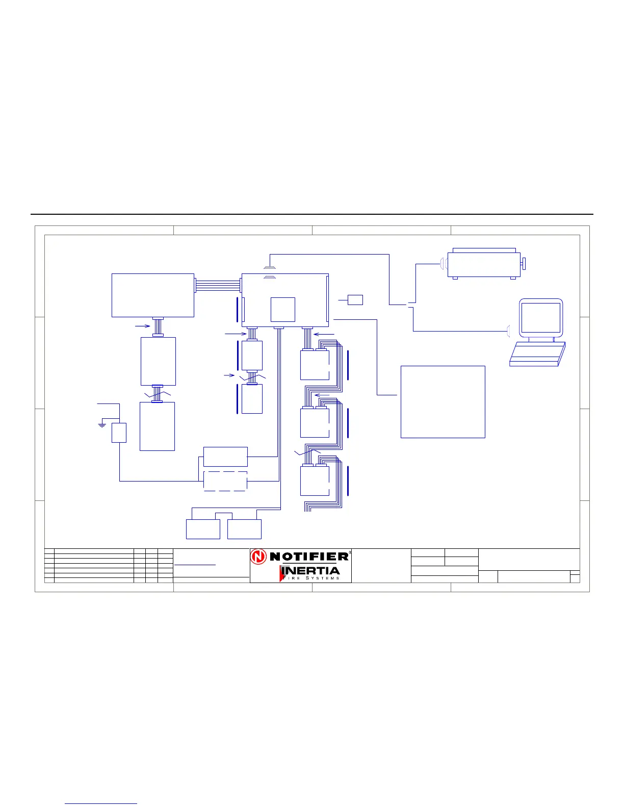
Block Connection Diagram
1
1
2
2
3
3
4
4
D D
C C
B B
A A
Rev
Size
Drg.
No.
Title
Sheet:
Drawn/
Traced
Engineer
Design
Approved
ThisDrawing must not beused forConstruction
unless signed asapproved
7 Columbia Court,
Norwest Business Park
Baulkham Hills NSW 2153
AUSTRALIA
Tel
Fax
Email: support@inertia.com.au
A4
No.
Revision - revise on CAD. Do not amend by hand Eng. App. Date
Copyright
Thisdocument is & shall
remain theproperty of
Notifier Inertia Fire Systems
Unauthorised use of this
document in any wayis
prohibited.
Drawing File No.
C
O
61 2 9894 1444
61 2 9899 4156
=DocumentFullPathAndName
Of:
IFS PCB2005
1 1
14/08/03 I.P.
D
L2600-1
IFS2600
BLOCK CONNECTION DIAGRAM
DISP
PCB816
MIMIC PANEL
12V BATTERY 12V BATTERY
+ +
-
-
MAIN PROCESSOR BOARD
MAIN TERMINATION BOARD
SERIAL PRINTER
240V/30V AC
100 VA
TRANSFORMER
2600/DHTX
100 VA
TRANSFORMER
240V
ISOL
S/W
MAINS SUPPLY
240 V AC
IFS PCB2004
RELAY
BOARD
IFS803
RELAY
BOARD
IFS803
RELAY
BOARD
IFS803
ZONE
EXP
PCB804
ZONE
EXP
PCB804
POWER
PCB2006
ZONE
INPUTS
1-8
ZONE
INPUTS
9-16
ZONE
INPUTS
32-40
8 RELAY
OUTPUTS
1-8
8 RELAY
OUTPUTS
9-16
8 RELAY
32-40
MAX 8 PCB803
OUTPUTS
CABLE C3
CABLE C5
CABLE C1
CABLE C3
CABLE C3
4 CORE CABLE
4 CORE CABLE
CABLE C8
MAX 120M
ZONE DISPLAYS 1-8
PANEL
POWER
D/HOLDER
POWER
OPTION
IN
IN
IN OUT
OUT
OUT
OUT
LAPTOP
P/N 130
16 ZONE
DISP
PCB816
IFS 810 MIMIC DRV
IFS 811B IND BRD
IFS 812 DISPLAY BRD
DB-9 FEMALE
(1 FOR EACH 8 ZONES)
OUTPUTS
8 ZONE
LAST DISPLAY CAN BE 8/16
OTHERS MUST BE 16 ZONE
CABLE C9
CABLE C32
B REVISED PART NUMBERS G.W. G.W. 9/3/04
PCB1125
BELL/ACF
3 CORE CABLE
SUPPLY
BOARD
RX, TX, GND
TX, CTS, GND
C Revised Printer Connection IP IP 18/8/05
D Removed Part Numbers IP IP 21/12/05
 Loading...


