Installation and Operations Guide
|
ACM-VLX/VLX/EXP/AXM
38
© Honeywell. All Rights Reserved. LT-VLXEXPAXMIOG Rev. 01
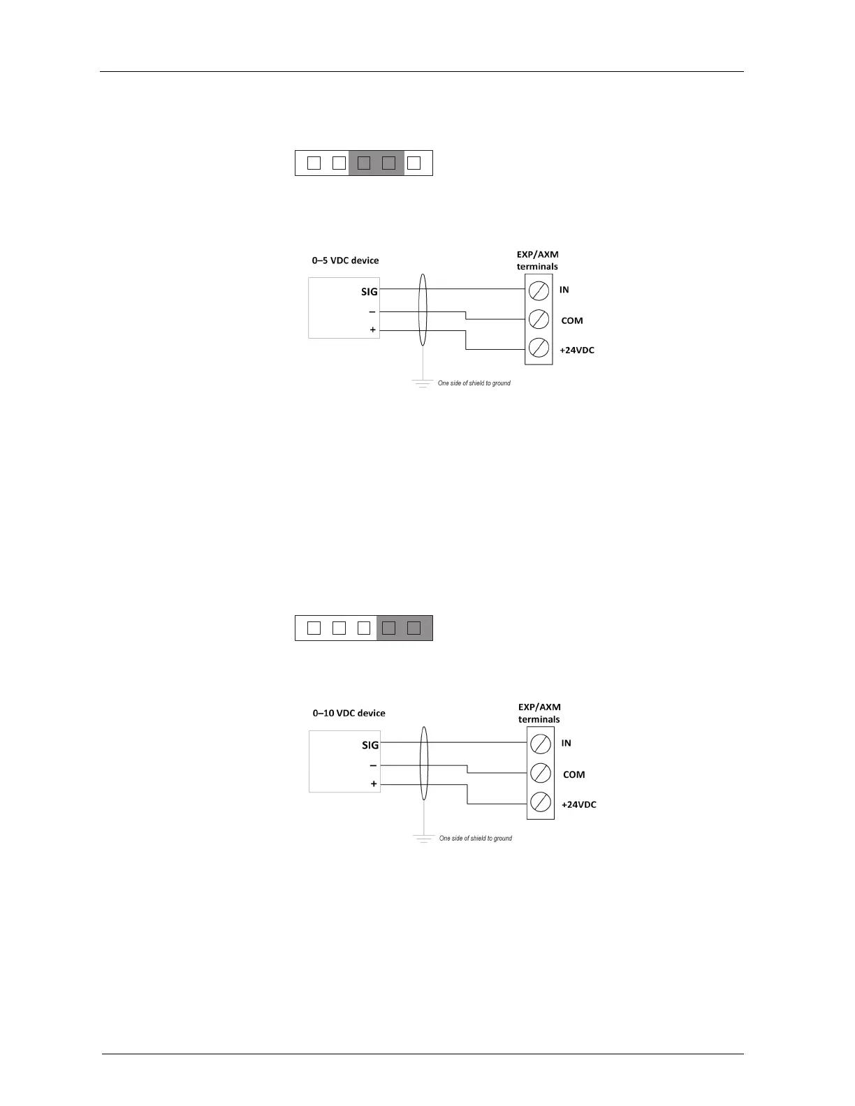
Set the input jumper to position 3.
0–10VDC inputs
For three-wire devices, the 20 VDC terminal on the EXP/AXM can provide a
power source to 250 mA max., which typically connects to the plus (+) terminal
on the device. Connect the device’s signal output, typically identified as Signal
or Output +, to the appropriate IN terminal. Connect the device’s output common
(typically identified as Output Common, Output –, or –) to the nearest COM
terminal.
Set the input jumper to position 4.
Solid-state switch inputs
Solid-state (transistor) switches can be wired to EXP/AXM input terminals. The
switch must be listed as acceptable for switching DC currents or for direct
connection to programmable logic controllers (PLCs) or DDC controllers. The
DC switch must use a transistor on the output. Maintain polarity.
Figure 20 Typical wiring for three -wire 0–5VDC device
Figure 21 Typical wiring for three -wire 0–10VDC de vice .
2345
1
2345
1
 Loading...


