Installation and Operations Guide
|
Hardware installation
© Honeywell. All Rights Reserved. LT-VLXEXPAXMIOG Rev. 01
39
Note It is helpful to test that the device produces appropriate count values as
wired to produce ON and OFF signals. Off-state leakage (if present) or other
factors may result in inappropriate software counts. See “Inputs (AIs and BIs)”
on page 59.
Set the input jumper to position 1.
Pulse-type inputs
Pulse-type inputs can be wired only to IN 1, IN 2, or IN 3 on EXPs/AXMs.
The device that generates pulse data should use contacts suitable for low current
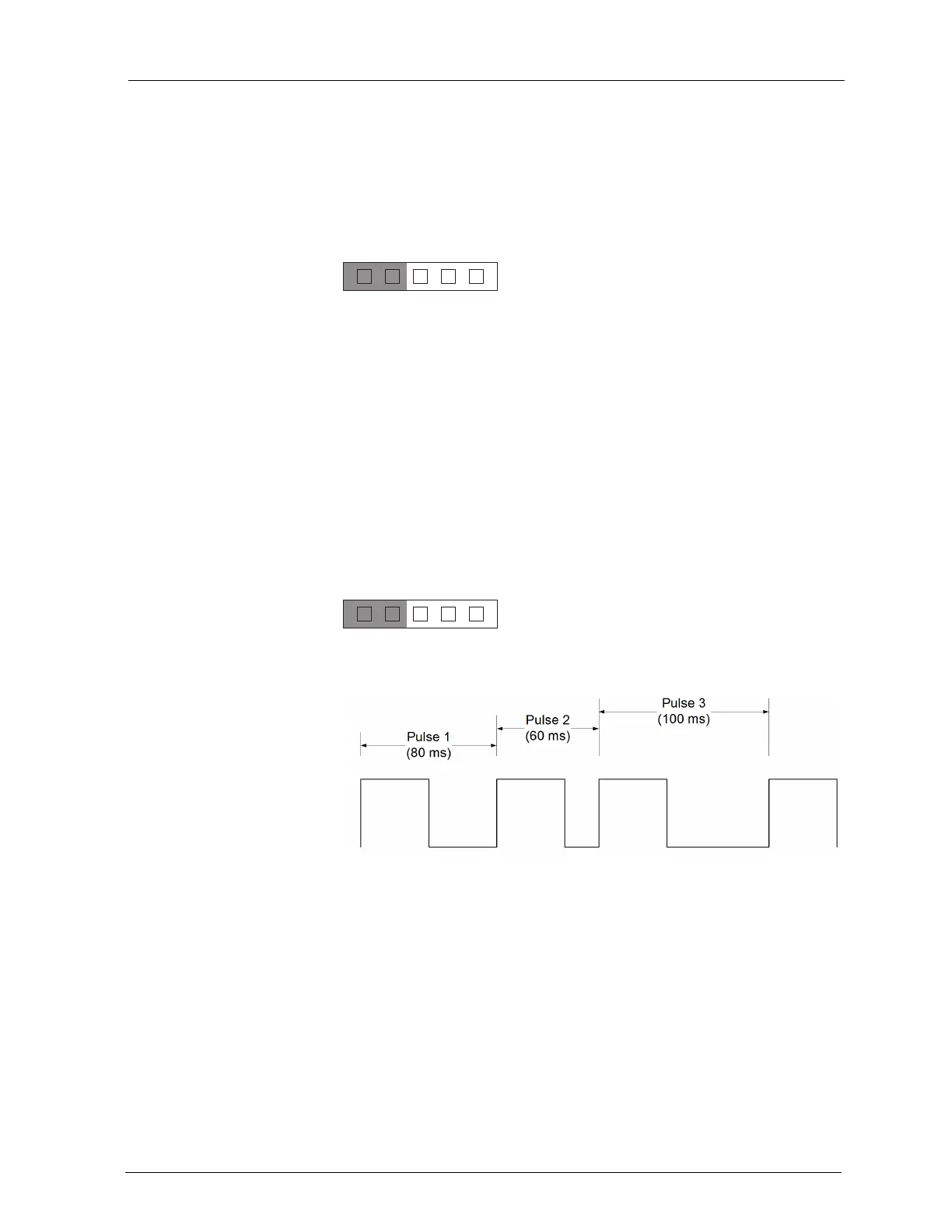
(gold contacts) or a solid-state (transistor) switch. Pulse width is measured from
successive rising edges of consecutive pulses (see Figure 22). The length of the
Pulse HIGH and LOW values must be at least 5ms to be reliably detected by the
EXP/AXM hardware. Thus, 10ms is the fastest specified rate.
A pulse HIGH duration of 2ms and a pulse LOW duration of 8ms would
technically get you a 10ms pulse length, but would not always get detected by
the hardware.
Set the jumper to position 1.
Figure 22 The VLX/ACM-VLX/EXP/AXM reads puls e data from s ucce s s ive
le ading e dge s
2345
1
2345
1
 Loading...


