20
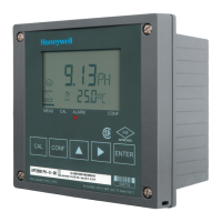
APT4000PH
Protective wiring of relay contacts
Relay contacts are subjected to electrical erosion. Especially
with inductive and capacitive loads, the service life of the con-
tacts will be reduced. For suppression of sparks and arcing,
components such as RC combinations, nonlinear resistors,
series resistors and diodes should be used.
1
2
3
1
2
3
Typical AC applications
with inductive load
1 Load
2 RC combination, e.g. RIFA PMR 209
Typical RC combinations
for 230 V AC:
Capacitor 0.1µF / 630V,
Resistor 100 Ohms / 1 W
3 Contact
Protective wiring of switching outputs
21
A: DC application with inductive load
B: AC/DC applications with capacitive load
C: Connection of incandescent lamps
A1 Inductive load
A2 Free-wheeling diode, e.g. 1N4007 (Observe polarity)
A3 Contact
B1 Capacitive load
B2 Resistor, e.g. 8 Ohms/1 W at 24 V / 0.3 A
B3 Contact
C1 Incandescent lamp, max 60 W / 230 V, 30 W / 115 V
C3 Contact
Warning!
Make sure that the maximum ratings of the relay
contacts are not exceeded even during switching!
Typical protective wiring measures
 Loading...

