EasyManua.ls Logo

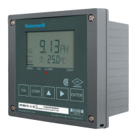
Honeywell APT4000PH - User Interface and Display

Honeywell APT4000PH
59 pages
To Next Page IconTo Next Page
To Previous Page IconTo Previous Page
Loading...
22
APT4000PH
User interface and display
1 Display
2 Mode indicators (no keys),
from left to right:
- Measuring mode
- Calibration mode
- Alarm
- Wash contact active
- Configuration mode
3 Keypad
4 Coding
5 Rating plate
6 Model designation
7 Alarm LED
User interface
23
1234 56 78910
11
12
13
1617
20
18
19
15
14
1 Mode code entry
2 Display of meas. variable *
3 Temperature
4 Current output
5 Limit values
6 Alarm
7 Sensocheck
8 Calibration
9 Interval/response time
10 Wash contact
11 Measurement symbols
12 Proceed with ENTER
13 Bar for identifying the device
status, above mode indicators,
from left to right:
- Measuring mode
- Calibration mode
- Alarm
- Wash contact active
- Configuration mode
14 Lower display
15 Manual temp indicator
16 Hold mode active
17 Waiting time running
18 Electrode data
19 Main display
20 Sensoface
* Not in use
Display

Related product manuals