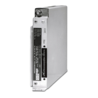
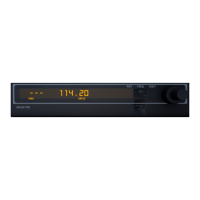
B KRA 405
Rev 6, June 2003 IM 006-00104-0006.dwd Page 2-7
2.4.4.3 Antenna Height
The antenna height above ground at touchdown is determined by information obtained
in the aircraft manual or by actually measuring the height of the antenna when the air-
craft is in touchdown configuration. The measurement cannot be made on a parked
aircraft since the landing gear is loaded. A simulated touchdown can be obtained by
jacking up the aircraft until the landing gear is unloaded as long as pitch attitude is also
taken into account.
2.4.4.4 Aircraft Installation Delay (AID) Selection and Calculation of Actual Antenna
Cable Length
Figure 2-8 is a graph used to determine the AID selection and the actual cable lengths
used in the installation. The cable lengths shown depend upon the AID used and an-
tenna height. The graph assumes the use of RG 393/U RF cable having a propagation
constant of 0.7. Cable lengths are critical and must be measured accurately. The fol-
lowing formula was used to produce the AID and installation cable length graph.
L = (AID-2H)B
Where: L = Total length in feet in RF antenna cable required for the
installation (L must be greater or equal to the minimum cable
length determined in paragraph 2.4.4.2.)
AID = Aircraft Installation Delay in feet (20, 40, and 57 feet)
H = Antenna height in feet
B = Cable propagation constant
NOTE: For equivalent types of 50 ohm coaxial cable other than RG 393/U, the
above equation must be used in order to determine the length of cable
and AID to be used.
The graph in Figure 2-8 and the formula above yield the total length of cable to be used
in the installation (i.e., the length of cable used from R/T to the transmit antenna plus
the length of cable from the R/T to the receive antenna). The cables need not be equal
in length. Excess cable should be coiled and secured to the aircraft. The transmit and
receive cables must be continuous with no intervening connections or breaks. Figure
2-9 contains instructions for assembly of TNC connectors to RG 393/U cable. Careful
construction of the coax connectors is extremely
important in a Radar Altimeter instal-
lation.
NOTE: Maximum length allowed for each cable is 17 feet (34 feet for both).
2.4.4.5 Aircraft Installation Delay (AID) Selection
Optimum performance of the KRA 405 system results using the 40 foot AID. It is rec-
ommended that for all installations where it is practical, the installer select the 40 foot
AID and calculate the cable lengths (paragraph 2.4.4.4) based upon this AID. Excess
cable can be coiled and secured to the air frame.
RELEASED FOR THE EXCLUSIVE USE BY: AIRCRAFT ELECTRONICS ASSOCIATION
UP536434
 Loading...
