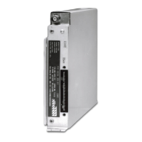
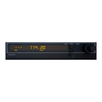
B KRA 405
Rev 6, June 2003 IM 006-00104-0006.dwd Page 2-9
In most cases altimeter installations that closely follow the suggestions of paragraph
2.4.3 will need no special equipment to check the integrity of the system, and the first
5 steps of paragraph 2.5.2 are sufficient to determine proper altimeter operation. How-
ever, if more than one of the suggestions in paragraph 2.4.3 cannot be complied with,
the probability increases that an installation problem will exist. In order to determine
whether an altimeter installation problem does exist, the tests in paragraphs 2.5.2 and
2.5.3 can take the place of a flight test. Agencies that install many altimeter systems
(including other manufacturers’ equipment) will find these test procedures quite help-
ful. For the majority of installation problems encountered, the procedures in paragraph
2.5.2 should prove sufficient.
2.5.2 KRA 405 RADAR ALTIMETER POST INSTALLATION TEST PROCEDURE
USING MICROWAVE ABSORBER
2.5.2.A Purpose of Test
The most common complaint (from an operational standpoint) against the KRA 405
Radar Altimeter System is that the indicator needle does not always stow behind the
mask after the test button is pressed and released, while flying above 2,500 feet AGL.
This problem is usually attributed to any one of several possible installation deficien-
cies, whereby an RF leakage path allows the 4.3 GHz transmitter output to bleed into
the system’s receiver, bypassing the normal antenna-to-ground-to-antenna path. The
following procedure duplicates a flight altitude greater than 2,500 feet AGL in order to
find these RF leakage paths.
2.5.2.B Required Equipment
The items listed below, or their electrical equivalent, may be used to conduct the tests
in this paragraph.
2.5.2.C Test Procedures
2.5.2.C.1 Turn on aircraft primary power.
2.5.2.C.2 Adjust the DH knob on the indicator to set the DH bug to 25 feet.
2.5.2.C.3 Depress the test button on the indicator. The altitude indicated should be 50
+/- 5 feet and the DH lamp should be out.
TABLE 2-3 RF Leakage Test Equipment (Microwave Absorber)
QTY TYPE CHARACTERISTICS REPRESENTATIVE MODELS
2 Microwave Absorber 1 ft square Anlon ML 74
2 TNC Female Barrel Americon 3180-0000
2 TNC Male Load Microlab FXR TA-SMT
RELEASED FOR THE EXCLUSIVE USE BY: AIRCRAFT ELECTRONICS ASSOCIATION
UP536434
 Loading...
