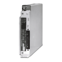
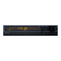
B KRA 405
Rev 6, June 2003 IM 006-00104-0006.dwd Page 2-10
2.5.2.C.4 Slowly advance the DH but until the DH lamp lights. The bug should be set at
50 +/- 5 feet at this time. Continue increasing the DH but setting. The DH
lamp should stay lit.
2.5.2.C.5 Release the test button. The indicated altitude should now be 0 +/- 5 feet.
NOTE: In some installations, the tolerances given here may be greater, due to
antenna location and a difference between aircraft touch down attitude
and parked attitude.
2.5.2.C.6 Place a one (1) foot square piece of the microwave absorber over each
KRA 405 Altimeter antenna. The pointer should go clockwise behind the
mask.
NOTE: It may be necessary to remove the aircraft from the hanger, away from
other aircraft and/or other sources of reflection in order to achieve an un-
lock condition (pointer behind mask) with the microwave absorber.
Complete steps 2 through 4. Release the test switch. The pointer should
again go behind the mask.
2.5.2.C.7 If the pointer did not stow in step 6 above, first exchange the antenna coaxes
at the R/T. Repeat step 6. If the pointer still does not stow, disconnect the
antenna cable from the R/T unit receiver or upper coax connector (transmitter
input, lower coax connector), and terminate the R/T with a 50 ohm load. The
pointer should stow. If it does not, place the microwave absorber over the
transmit (receiver) antenna. If the pointer still does not stow, disconnect the
antenna coax from the transmit (receiver) antenna and connect a 50 ohm mi-
crowave load to the antenna coax. Rebond the antenna if the pointer is now
stowed. If not, terminate the transmit (receiver) port of the R/T. Check the
items in paragraph 2.4.3 pertaining to the antenna coax if the pointer is
stowed. If not, the R/T unit should be bench tested.
2.5.2.C.8 Repeat step 7 terminating the transmit port of the R/T and reconnecting the
receiver coax and antenna. Use the instructions in parentheses.
2.5.3 KRA 405 RADAR ALTIMETER POST INSTALLATION TEST PROCEDURE
USING SIMULATED ALTITUDES
The procedures in paragraph 2.5.3.1 simulate an actual altitude and, therefore, test
the RF portion of the altimeter. The procedures in paragraph 2.5.3.2 test all circuit
functions except the RF portion.
2.5.3.1 Test Method 1
KRA 405 Radar Altimeter Post Installation Test Procedures using 1000 Foot Delay
Line
2.5.3.1.A Purpose of Test
This test simulates an actual altitude of 1000 feet AGL with various return signal
strengths. Low power output, poor coax cables, poor connectors and poor R/T perfor-
mance can be found using this method.
RELEASED FOR THE EXCLUSIVE USE BY: AIRCRAFT ELECTRONICS ASSOCIATION
UP536434
 Loading...
