Description of Extra Parts LION System
EN1Z-0921GE51 R0709
66
XS814 Auxiliary Terminal Package
Features
•
Type: XS814 Auxiliary Terminal Package
• For mounting onto already installed pluggable
I/O modules in order to equip them with additional
terminals.
• Each unit consists of 2 terminal blocks (the "A" block and
the "B" block), each with 7 terminals with a maximum
load of 12 A.
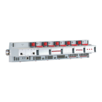
Fig. 93 XS814 Auxiliary Terminal Package
Terminal Assignment
1234
5
67
A1 A2
A3
A4
A5 A6
A7
1234
5
67
B1 B2
B3
B4
B5 B6
B7
Fig. 94 Terminal assignment and internal connections of
XS814 Auxiliary Terminal Package
XS830 Auxiliary Terminal Package
Features
•
Type: XS830 Auxiliary Terminal Package
• For mounting onto the top and/or bottom of already-
installed CLIOP830A mixed I/O modules in order to equip
them with additional terminals.
• Each unit consists of two groups of terminal blocks
(the "A" block and the "B" block), each with nine
internally-connected push-in terminals with a maximum
load of 12 A.
A1 A2 A3 A4 A5 A6 A7 A8 A9 B1 B2 B3 B4 B5 B6 B7 B8 B9
Fig. 95 XS830 Auxiliary Terminal Package
Terminal Assignment
1 12 23 34 4
5 5
6 6
A1 B1A2 B2A3 B3A4 B4
A5 B5
A6 B6A7
A8 A9
B7
B8 B9
7 8 9 7 8 9
Fig. 96 Terminal assignment and internal connections of
XS830 Auxiliary Terminal Package
XS831 Auxiliary Terminal Package
Features
•
Type: XS831 Auxiliary Terminal Package
• For mounting onto the top and/or bottom of already-
installed CLIOP830A mixed I/O modules in order to equip
them with additional terminals.
• Each unit consists of two groups of four pairs of push-in
terminals (A1B1, A2B2, … A8B8, each with a 499Ω
resistor) for converting 0…20 mA signals (maximum load
per resistor = 25 mA) into 0…10 Vdc signals, and one
push-in ground terminal per group. See also Fig. 98.
Note
The ground side of each of the eight incoming 0…20 mA
signals (A1B1, A2B2, … A8B8) must be connected to a
ground terminal.
A1 B1 A2 B2
A3 B3
A4 B4 G1 G2
A5 B5 A6 B6
A7 B7
A8 B8
Fig. 97 XS831 Auxiliary Terminal Package
Terminal Assignment
1 12 2
3 3
4 4
5 5
6 6
A1 B1 A2 B2
A3 B3
A4 B4 G1
A5 B5 A6 B6
A7
A8
B7
B8
G2
7 8 9 7 8 9
Fig. 98 Terminal assignment and internal connections of
XS831 Auxiliary Terminal Package
 Loading...
