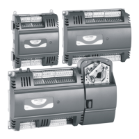
LION System Mounting/Dismounting Modules
17 EN1Z-0921GE51 R0315
► Angle the terminal socket at the upper edge of the DIN
rail until it snaps in.
► Swing the terminal socket down and apply gentle force
until it snaps into position with an audible "click".
► Position controller module and terminal sockets flush with
one another along the rail.
► If desired, mount stoppers at the ends of the rail to
prevent sliding.
Fig. 17 Mounting terminal sockets
NOTE: Take care to not bend the Omega clamp, which
serves to establish the electrical contact with the
DIN rail and which located on the back of the
terminal socket.
Connecting Sockets
Controller, terminal sockets, and mixed I/O modules on the
same DIN rail can be connected mechanically and
electrically with bridge connectors.
Controller and terminal sockets on different DIN rails must
be connected using cables, see Fig. 14 and page 23.
NOTICE
Risk of malfunction!
► Wire Panel Bus I/O modules and LONWORKS Bus
I/O modules separately.
► When using both Panel Bus and LONWORKS Bus
I/O modules in a LION System, L
ONWORKS Bus
I/O modules must be connected to the controller via
LON terminals 11 … 14.
Position the bridge connector on terminals 71 … 74 of the
right hand terminal socket or mixed I/O module or controller
and on terminals 75 … 78 of the left hand terminal socket or
mixed I/O module or controller. Then press the bridge
connector down.
Fig. 18 Connecting terminal sockets with bridge
connector
NOTE: Bridge connectors transmit both communication
signals and power supply between modules.
Removing bridge connectors will thus interrupt
the transmission of both communication signals
and power supply between the modules.

 Loading...