CLASS 320 METER
19 62-0397-02
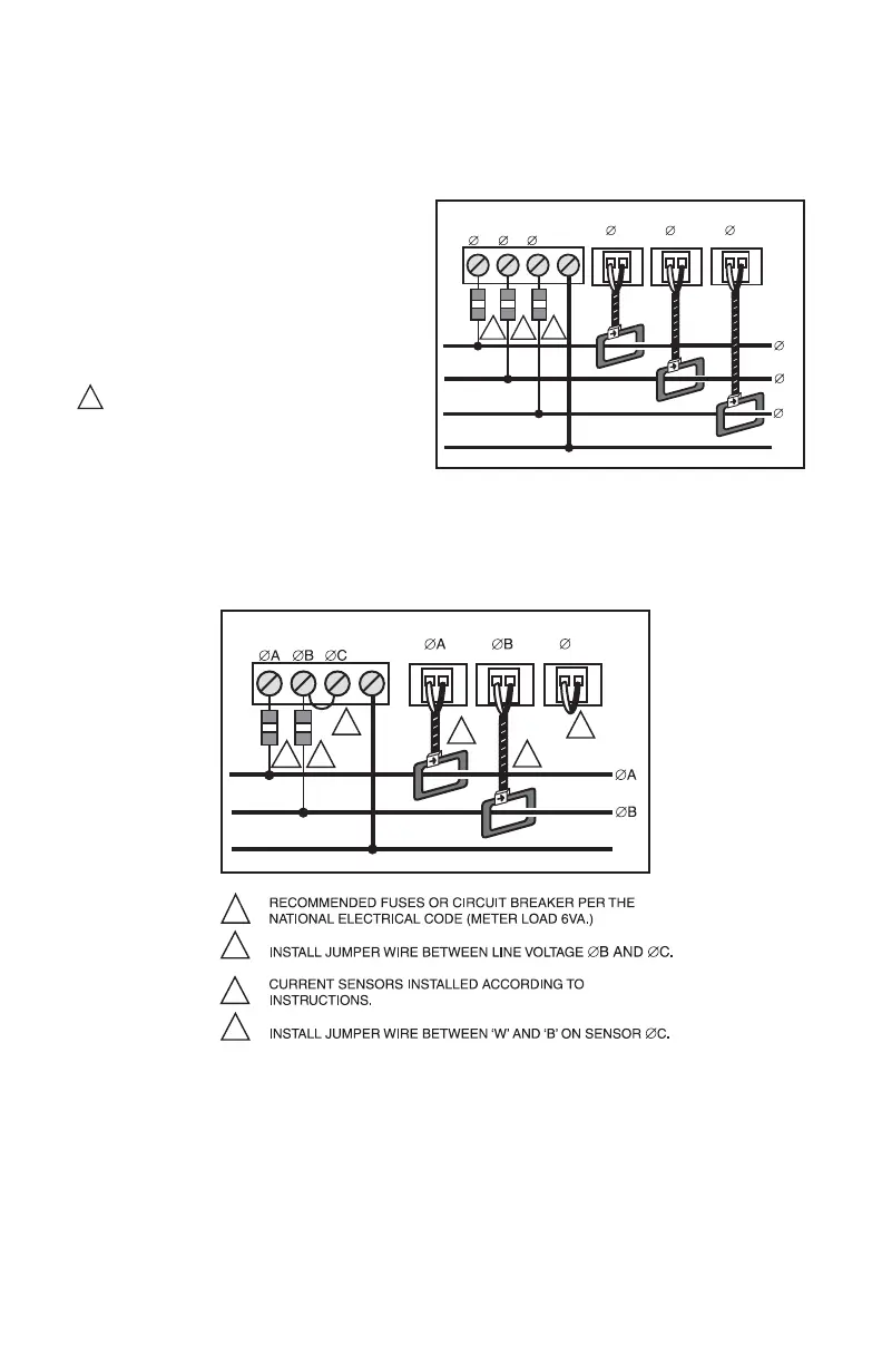
6.5 Main Power & Current Sensor Wiring Diagram
Fig. 9. 3-phase- 4 Wire Installation Diagram
Fig. 10. Single-Phase, 3-Wire, Installation Diagram
A B
LINE VOLTAGE
CURRENT SENSORS
A
N
B
LOAD SOURCE
M34642
3-PHASE, 4-WIRE INSTALLATION DIAGRAM
NOTES:
LINE VOLTAGE CONNECTIONS: #14-22 AWG
SENSOR CONNECTIONS: B = BLACK LEAD W = WHITE LEAD
NEUTRAL NOT USED IN DELTA SYSTEM. REMOVE NEUTRAL TERMINAL
BLOCK SCREW FOR DELTA SYSTEMS.
1/10A 600 VAC INLINE FUSE PER CONDUCTOR. LITTLEFUSE PART
NUMBER KLDR, 100.
1
1
1
C
1
C
A B C
W B W B
N
W B
LINE VOLTAGE
CURRENT SENSORS
N
LOAD SOURCE
1
1
1
2
C
W B W B
N
W B
2
3
3
4
3
4
 Loading...


