DB7110U UNIVERSAL HEAT PUMP DEFROST CONTROLLER
7 34-00032—01
USER INTERFACE
The user interface consists of three buttons, two LED’s, and 4 7-segment digits. The two left digits generally
represent the category of what is being displayed while the two right digits represent the value or setting of the
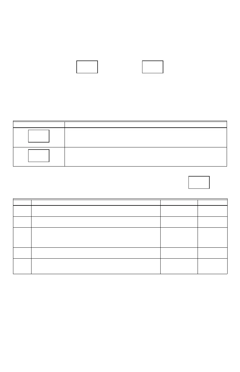
category. The exception is in the event a value requires 3 digits such as a temperature higher than 99F as shown
below with two “termination temperature” values of 90F and 100F.
Fig. 12. Two example values of configuration option 2 (Termination Temperature).
The “o” button advances to the next screen while the and buttons are used to adjust the value of each
parameter.
Note that after one hour without a button press, the 7-segment display will turn off to save power. A button must
be pressed to turn the display on again.
Table 3. Status Screens.
The configuration screens are numbered parameters where numbered parameter has a selectable value
according to the table below.
For example, would represent Parameter 1 (Defrost Enable Temperature) set to 35 (degF).
Display Description
Current Fault(s) Present.
Right digits blank if there is no fault.
and to scroll through active faults.
Fault History
and to scroll through history.
Press and hold for more than two seconds to clear all inactive faults.
Table 4. Configuration Screens.
Display Description Range Default
1 Defrost Enable Temperature
Coil temperature where defrost functionality is active.
30degF-36degF 35degF
2 Termination Temperature.
Coil temperature where defrost is terminated.
70degF-100degF 70degF
3 Defrost Cycle Time
Time the coil temperature is below the Defrost Enable
Temperature before a defrost is triggered if in timed mode
(no outdoor air sensor present).
30-120 minutes 30 minutes
4Short Cycle Delay Time
Minimum off time between compressor cycles.
0-5 minutes 3 minutes
5 Reversing Valve System Type
O = reversing valve energized in cool.
B = reversing valve energized in heat.
O or B O
90
1
00
M37659
2
2
4
F
M37660
H 11
F
M37661

 Loading...


