ENS7003R0 KO06 2010
Flame signal is present
●◐○○○○◐◐
Air flow switch goes OFF
●◐◐○○○○◐
Ignition Trial
Ignition failure (flame signal is present during ignition-trial).
●○◐○○○○◐
Air flow switch goes OFF
●◐○◐○○○◐
Pilot
No flame signal
●○○◐○○◐◐
Air flow switch goes OFF
●◐○○◐○○◐
Main ignition Trial
No flame signal
●○○○◐○◐◐
Air flow switch goes OFF
●◐○○◐○○◐
Main ignition Stability
No flame signal
●○○○◐○◐◐
Air flow switch goes OFF
●◐○○○◐○◐
Run
No flame signal
●○○○○◐◐◐
No power is supplied to NO.3 terminal because of inter relay contact
failure.
●◐○◐◐○○◐
Flame signal is present for more than 10 seconds after heat demand
has ended.
●○○○○○◐◐
Post-purge
Air flow switch keeps ON more than 2 minutes after post-purge.
●◐○○○○○◐
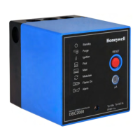
*1 For LED indication, ○ means ‘off’ ● means ‘illuminated’ ◐ means ‘blinking’.
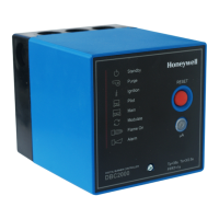
The LEDs are arranged in the following order: Standby, Purge, Ignition, Pilot, Main, Modulate, Flame and Alarm at the
left front side of the DBC2000E
.*2 If an error occurs during Standby, the DBC2000 will not lock-out but LEDs indicate the current error status.
In this case, the DBC2000 cannot start before the error is resolved.
 Loading...
