SPECIFICATIONS
Table 1: Model Selection Guide
Model
Description / Application Supply voltage
DBC2000E1xxx Standard model 115 or 230Vac
DBC2000E2xxx Enhanced model 115 or 230Vac
The Enhanced Model includes remote bus communication and a Valve Proofing System.
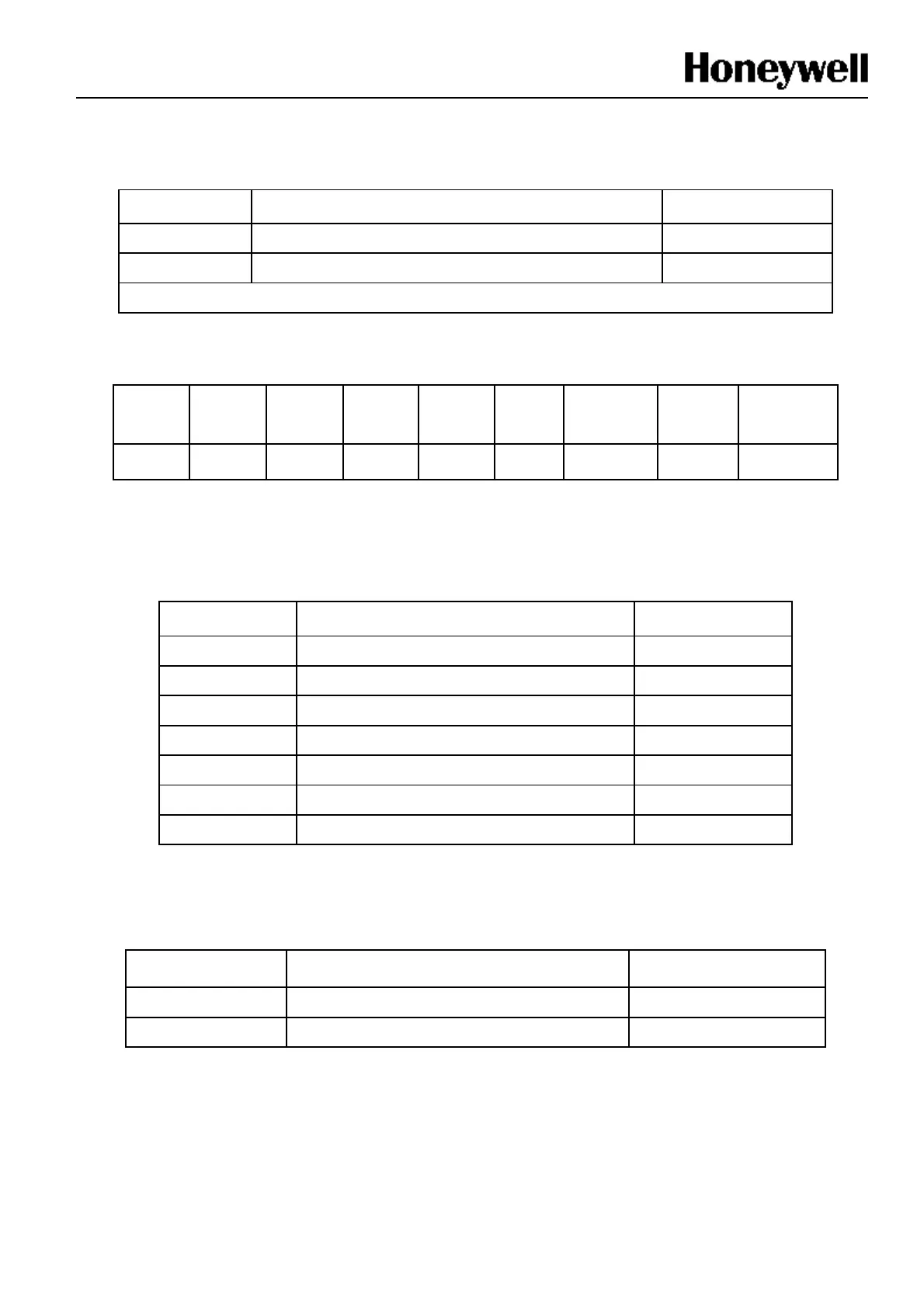
Table 2: Sequence timing
Waiting
for AFS
Waiting
for HF
Pre-purge
Ignition
trial
Pilot-
only
Main
trial
Main
stabilized
Post
purge
Flame failure
response
5m max 5m max 35sec 3sec 3sec 3sec* 4 sec* 15 sec** Max. 1sec
* set to 0sec if DBI function is enabled
** set to 0sec if no postpurge feature is enabled
Sequence at flame failure: immediate lock out
Table 3: Contact ratings
Terminal
Load Contact rating
3 Blower / Fan 3A @ cosφ=0.6
4 Ignition transformer 3A @ cosφ=0.6
5 Intermittent pilot or main (DBI) valves 3A @ cosφ=0.6
6 Interrupted Pilot 3A @ cosφ=0.6
7 Main (PI) valves 3A @ cosφ=0.6
8, 9, 10, 11 Control motor 0.5A @ cosφ=0.6
21 Alarm 0.5A @ cosφ=0.6
Total load (based on set): Max 8A (Internal Fuse : 10A)
Total load (based on terminal 4,5,6,7): Max 5A (Internal Fuse : 6.3A)
Table 4: Flame detection systems
Detector type
Flame detector model No. Standard flame current
UV detector C7027A, C7035A, C7044A
4㎂ min.
Flame Rod Rectification type Flame rod, or C7012A/G
18㎂ max.

 Loading...


